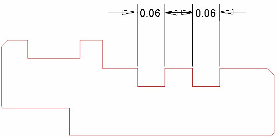
This section describes how to program the two grooves on the turned diameter of the part:
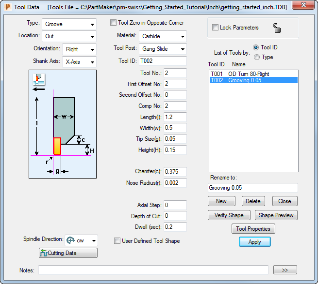
Before programming this toolpath, you must create a new tool, as no suitable tool currently exists in the Tools database.
- Click the
Tools button to display the
Tool Data
dialog.

- On the
Tool Data dialog, click
New,
then complete the dialog as shown:
- Select a colour for the toolpath from the Color Palette, then click the
New Profile Group button to display the
Profile Group Parameters, Turn dialog.

- Complete the
Profile Group Parameters, Turn dialog, as shown:
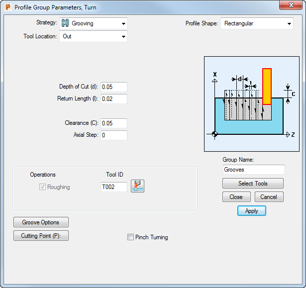 Tip: Use the Select Tools button to select the new tool you created in Step 2.
 - Click the
Define Profile
 button, then click the
End of an Element Snap Mode button:
button, then click the
End of an Element Snap Mode button:

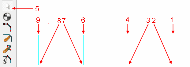
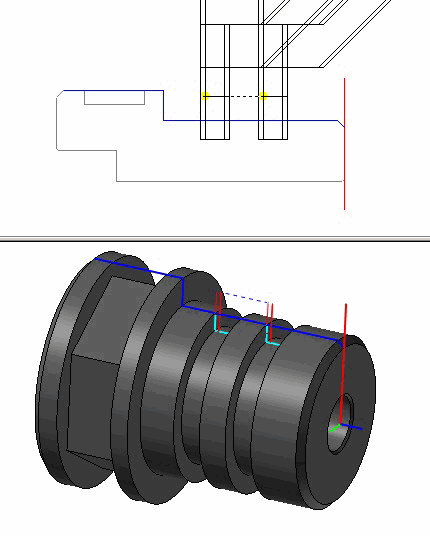
- You can now define the profile using snap points. Follow the order shown below, including clicking the
Selection button (see 5) when you have finished the first profile, to ‘break’ the profiles into two distinct pieces:
- To verify the toolpath, click the
Verify Work Group Toolpath button, then click
OK on the
Face Window Verification Options dialog.

You can now visualize the toolpath:
- Click the
Hide Every Toolpath button to remove the verification details from the display.
