If you have selected Box stock, the following settings are available on the Multiple Stocks Machining dialog:
Face Designation in Multiple Stocks Machining — Use these settings to specify whether the machining operations programmed in the current Face window are machined on the same stock as operations in other Face windows, or on different stock. This ensures that the correct stock is used during simulation.
-
Independent, Add New Stock — Select this option if the toolpaths created in the current Face window are machined on a separate stock to other Face windows. Independent stocks are shown separately on the Standard and Tombstone machining table in PartMaker's 3D simulation.
This option is available only when you have the Mill XY Plane machining function selected on the Setup dialog.
When you select this option, PartMaker creates a Face that is parallel to the tombstone or standard table face.
Each Face window using an Independent Stock should have a different Work Offset value set in the Setup dialog.
-
Dependent, Use Stock Defined for Face — Select this option if the toolpaths created in the current Face window use an existing stock that is already in use by another Face window during simulation, then select the designated Face window from the drop-down list box.
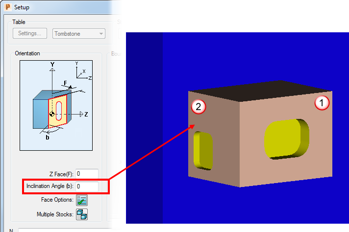
When you define the Face plane of a 4-axis dependent face on a tombstone table from the solid model (using Solids > Face Coordinate System > Define Face Plane), PartMaker automatically calculates the inclination angle for the dependent face and displays this value in the Inclination Angle field on the Setup dialog. For example, the FRONT independent face shown below is specified at an Index Angle of 0 degrees. When defining the Face plane of a 4-axis dependent face from the solid model, PartMaker calculates that this face needs an inclination angle of -90 degrees from the FRONT stock work side.
 Independent face (FRONT)
 Dependent face
Stock Orientation in Multiple Stock Machining — Using the settings in this area of the dialog, you can specify different Face windows for different sides of the box and program them in the orientation needed to produce the NC code required to reflect how things will be set up on the table. Setting these options also enables PartMaker to connect the machining functions together to show the correct finished part when using PartMaker simulation.
- Unfolded View — Click to display an unfolded representation of the stock work sides. You can use this for reference when designating the required Face Orientation for the finished part.
Local Coordinate System
-
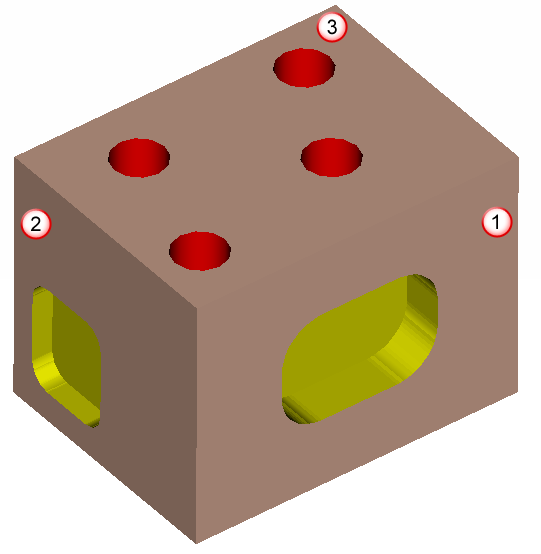
Stock Work Side — Select which side of the stock is facing the tool when mounted on a standard or tombstone table. This is defined for an Independent face only. The image below shows different stock work sides for a part.
Each part must include a Face window with a FRONT orientation.
 FRONT LEFT
 TOP
TOPStock Positioning Angle on Machining Table — Select an angle to specify how stock for the Face window is oriented during machining when compared to finished part. The value you select does not affect the NC code, but PartMaker uses this value to rotate the toolpath during simulation. If you are rotating the part to 90 or 270 degrees, you also need to adjust the coordinates of the boundaries in the Setup dialog.
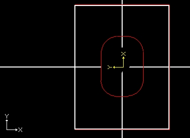
The following example shows the FRONT Face (shown above) programmed at a +90 orientation with respect to the solid model, so you need to select a value of 90 degrees as the Stock Positioning Angle on the Machining Table. The yellow coordinate system shows the solid model's origin, while the white coordinate system shows the programmed coordinate system. When transferring geometry from a solid model, it is transferred in the programmed coordinate system.