Use the Steep and shallow finishing page to specify settings for calculating a shallow boundary so that PartMaker creates a Constant Z toolpath in the steep regions of a model and a 3D offset or Raster toolpath in the shallow regions.
The following settings are available:
Order —Select the order in which the steep and shallow regions are machined.
- Top First — Select this option to machine from the top regions downwards. If you have a boss, the shallow regions at the top of the boss are machined before the constant Z (steep) regions down the sides.
- Steep First — Select this option to machine the steep regions before the flat regions. If you have a boss, the constant Z (steep) regions are machined before the shallow regions.
Additional stock — Use this option to help with ordering when machining between two steep walls so PartMaker produces a safe order with the level of stock specified here. Providing the passes are within the distance specified, an alternating toolpath is created, machining at one machining-level height on one wall, and then at the same height on the neighboring wall before descending to the next machining-level height. If the Additional stock is zero, PartMaker uses a default value that is one tenth of the tool radius.
Threshold angle —Enter the surface slope, measured from the horizontal, that determines the split between constant Z (steep) and shallow machining.
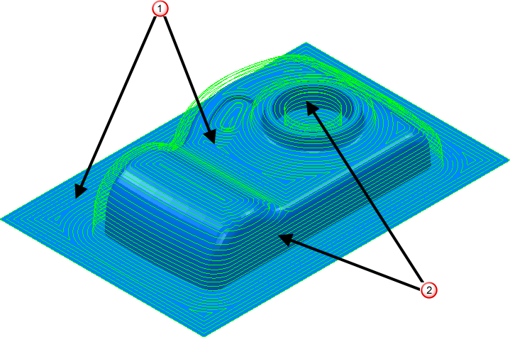
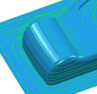
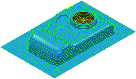
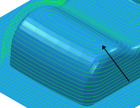
 Shows the 3D Offset toolpath in the shallow areas.
 Shows the Constant Z toolpath in the steep areas.
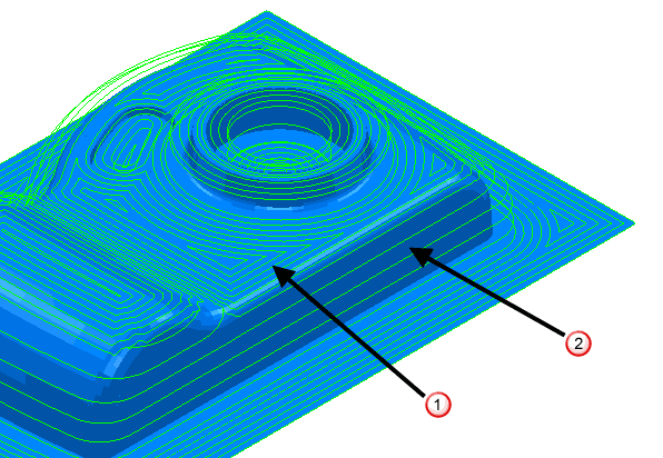
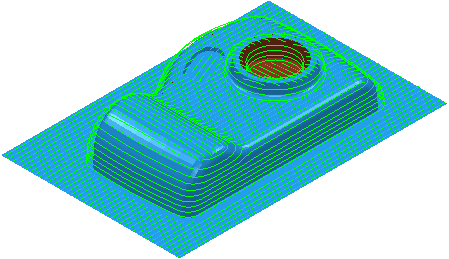
Steep shallow overlap — Enter the size of the overlap area where constant Z (steep) and shallow machining occur. This minimizes marks on the model caused by a sudden switch from constant Z to shallow machining.
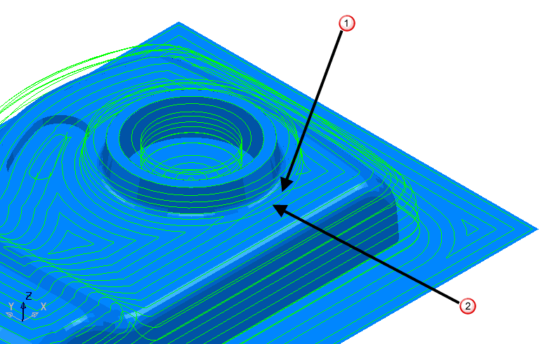
Shows the 3D Offset toolpath overlapping into the steep areas.
Shows the Constant Z toolpath.
Steep — The options for the constant Z portion of the toolpath.
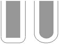
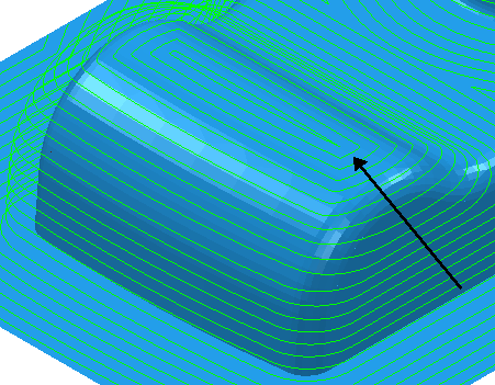
Spiral —Select this option to create a spiral path between two consecutive closed contours.
This minimizes the number of lifts of the tool and maximizes cutting time while maintaining more constant load conditions and deflections on the tool.
Select Spiral to convert this:
to this:
Cut direction — Select the milling technology.
-
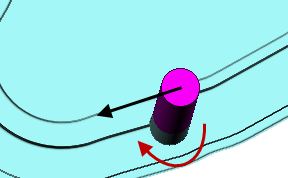
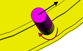
Climb — Select to create toolpaths using only climb milling, where possible. The tool is on the left of the machined edge when viewed in the direction of tool travel.
-
Conventional — Select to create toolpaths using only conventional or upcut milling, where possible. The tool is on the right of the machined edge when viewed in the direction of tool travel.
- Any — Select to create toolpaths using both conventional and climb milling, as appropriate. This minimizes the tool lifts and tool travel.
Stepdown —Enter the constant stepdown value between successive machined levels.
— Shows the 3D Offset toolpath stepover in the shallow areas.
— Shows the Constant Z toolpath stepdown in the steep areas.
Calculate using cusp — Select this option to determine the stepdown by the Cusp height, with a maximum stepdown determined by the Maximum stepdown value. When deselected, the stepdown between successive Z heights has a constant value equal to the Minimum Stepdown value.
Cusp height — Use this setting to specify the stepdown so that the height of the material left between Z Heights does not exceed the Cusp Height. However, if the calculated value is smaller than the Minimum Stepdown, it is set to Minimum Stepdown.
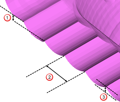
Stepdown
Stepover
 Cusp height
Maximum stepdown — Enter the maximum allowable stepdown when calculating the stepdown using the cusp height. This prevents excessive stepdown on vertical walls.
Shallow — The options for the raster/offset portion of the toolpath.
Spiral —Select this option to create a spiral path between two consecutive closed contours.
This minimizes the number of lifts of the tool and maximizes cutting time while maintaining more constant load conditions and deflections on the tool.
Select Spiral to convert this:
to this:
Cut direction — Select the milling technology.
-
Climb — Select to create toolpaths using only climb milling, where possible. The tool is on the left of the machined edge when viewed in the direction of tool travel.
-
Conventional — Select to create toolpaths using only conventional or upcut milling, where possible. The tool is on the right of the machined edge when viewed in the direction of tool travel.
- Any — Select to create toolpaths using both conventional and climb milling, as appropriate. This minimizes the tool lifts and tool travel.
Stepover —Enter the distance between successive machining passes.
Shows the 3D Offset toolpath stepover in the shallow areas.
Shows the Constant Z toolpath stepdown in the steep areas.
Type — Select whether PartMaker creates a Raster or Offset toolpath in the shallow regions.
-
Offset
-
Raster
As a general rule, use raster on open-edged parts and 3D offsets at the bottom of a pocket.
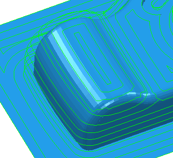
Smoothing —Select this option to smooth offsets of toolpath segments over the model.
Select the Smoothing option to convert this:
to this:
Tolerance — Enter a value to determine how accurately the toolpath follows the contours of the model.
Thickness — Enter the amount of material to be left on the stock within tolerance. Thickness is applied as an offset to the tool in all directions: