The Surface Info – Plane dialog displays geometric information about the currently selected planar surface.
To display this dialog, double-click a planar surface on a solid model.
The following settings are available:
Angle with XY Plane — Displays the angle made by the selected surface with the XY plane.
C Angle — Displays the indexing angle required to machine this surface. PartMaker assumes that the Z axis of the Part Coordinate System is the Indexing Axis, except when using 4-axis rotary milling tables when PartMaker assumes that the X axis of the Part Coordinate System is the Indexing Axis.
B Angle — Displays the angle between the normal to the plane and Z axis of the Part Coordinate System after indexing the part through the C Angle. This angle is useful for machines with a B-axis.
X Offset, Y Offset, Z Offset — These fields display the perpendicular offset distance from the origin of the Part Coordinate System to the selected surface along the X, Y and Z axes respectively:
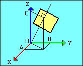
where:
X Offset = OA
Y Offset = OB
Z Offset = OC
Transfer Geometry
- Set Face Plane as Selected — Select to set the Face Plane of the current window to be parallel to the currently selected planar surface. This is not applicable when using the Project Outline button.
-
Set Boundaries
— Select to reset the current Face boundaries to encompass the transferred geometry. This is not applicable when using the
Project Outline button.
For PartMaker/Turn and PartMaker/Turn-Mill with a cylindrical stock, selecting this option resets the diameter and the length of the part, taking into consideration the bounding box of the solid model.
When milling with a rectangular stock, selecting this option resets the rectangular Face boundaries and the height of the stock based on the bounds of the transferred geometry and the height dimension of the solid model that corresponds to that particular milling face.
-
Transfer Geometry
— Click to transfer the planar geometry on the selected planar surface into the current Face window.
The button is available only if the Face plane of the current Face window is parallel to the orientation of the selected planar surface. For example, if the selected surface is parallel to the XY plane, the matching Face windows would be Mill XY Plane, Mill Polygon, Mill End Index and Mill End Polar.
If the selected surface can be machined using the current Face window, but is not parallel to the Face plane, you can select Set Face Plane as Selected to set the Face plane to be parallel to the selected surface before transferring the geometry.
If the geometry being transferred contains spline curves, PartMaker displays the Convert Curved Edges dialog, where you can specify whether PartMaker converts the curves into arcs or lines.
Project Outline — Click to project the peripheral edges of the selected surfaces onto the current PartMaker Face window. Any edge that is a curve is broken down into lines, based on the Curve Tolerance. PartMaker projects the outline in a direction perpendicular to the Face Plane of the current Face window.
If the geometry being transferred contains spline curves, PartMaker displays the Convert Curved Edges dialog where you can specify whether curves should be approximated into arcs or lines.