Use the Tool axis page to control the orientation of the tool axis in 5-axis simultaneoustoolpaths.
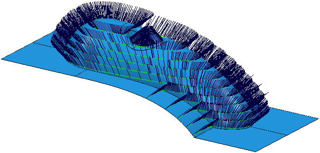
To display the tool axis for a toolpath on a solid model, select Solids > Set View > Show Tool Axes or select Show Tool Axes from the Set Visibility button on the Solids window toolbar.
The following settings are available:
Tool axis
Select an option to define the tool orientation. The options available for selection vary depending on the surface machining strategy being used.
Vertical — The tool stays aligned normal to the Face plane. This option is available when using Raster 3D Offset, Constant Z or Pattern finishing strategies.
Lead/Lean — The tool is at a fixed angle normal to the Face plane. The tool is dropped down the Face plane normal onto the model. This option is available when using Raster 3D Offset, Constant Z, Spine, or Pattern finishing strategies.
- Lead — Enter the tool angle, relative to the Face plane normal, in the feed-rate direction (the direction of travel).
- Lean — Enter the tool angle, relative to the Face plane normal, perpendicular to the feed-rate direction (the direction of travel).
Towards point — The tool tip tries to point towards the fixed point. The angle of the tool constantly changes. This option is available when using Constant Z, or Pattern finishing strategies.
The head of the machine tool moves significantly, while the tip of the tool remains relatively still. This option orientates the tip of the tool towards a point.
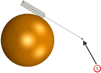
 User-defined point. The tool axis always passes through this point.
From point — The tool tip tries to point away from the fixed point. The angle of the tool constantly changes. This option is available when using Constant Z, or Pattern finishing strategies.
The tip of the tool moves significantly, while the head of the machine tool remains relatively still. This option orientates the tip of the tool away from a point.
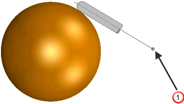
User-defined point. The tool axis always passes through this point.
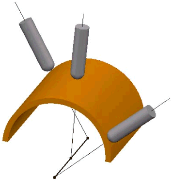
Radial — When selected, the tool tip tries to point towards the part's rotary axis. The angle of the tool constantly changes. This option is available when using Raster 3D Offset, Constant Z, Spine, or Pattern finishing strategies.
The head of the machine tool moves significantly, while the tip of the tool remains relatively still. This option orientates the tip of the tool towards a line representing the part's rotary axis.
Automatic — PartMaker uses the geometry to determine the tool axis. This option is available when using Swarf or Wireframe swarf finishing strategies.
Lead/Lean angles
Enter the angle of the tool from the vertical when using a Tool axis of Lead/Lean. The tool is at a fixed angle relative to the local normal to the toolpath. The local normal is going to vary as you go along the toolpath, at each point of the toolpath and relative to the direction of the toolpath at each point.
You can specify two different angles - Lead and Lean. If you specify both a Lead and a Lean angle, the Lead Angle is applied first in the direction of the move, and then the Lean Angle is applied from this rotated position towards a vector perpendicular to the move.
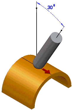
Lead — Enter the angle of the tool axis in the direction of travel. It is measured from the perpendicular to the direction of travel. 0 is vertical. Typically, this is used to avoid cutting at the center of a ball nosed tool on flattish areas. A typical
Lead Angle is 15.
is vertical. Typically, this is used to avoid cutting at the center of a ball nosed tool on flattish areas. A typical
Lead Angle is 15.
Lead angle, which is in the direction of travel. In this example the angle is in the ZX plane.
 Direction of travel.
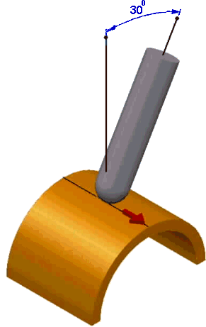
Lean — Enter the angle of the tool axis at right angles to the direction of travel. 0 is vertical. Typically, a
Lean Angle is used to avoid the tool holder colliding with the part, to avoid collisions caused by a step, or to allow you to use a smaller tool when machining up to a step.
Lean angle, which is perpendicular to the direction of travel. In this example the angle is in the YZ plane.
Direction of travel.
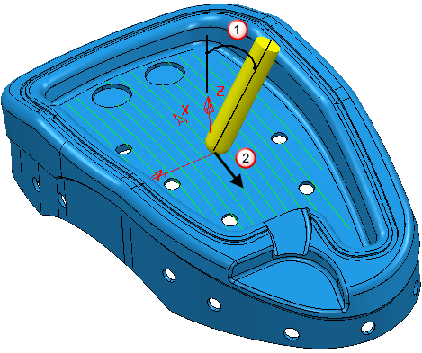
Point — Enter the fixed point location when using a Tool axis of Towards point or From point.
Mode — Select the reference direction for the tool axis from which PartMaker measures the lead and lean angles. This option is available only when a Tool Axis of Lead/Lean is selected.
With a Tool Axis of Lead/Lean, the Lead angle is measured with respect to the reference direction in the direction of travel. The Lean angle is measured with respect to the plane containing the reference direction and the tool movement direction. So, with a Lead of 0 and a Lean of 0, the tool is aligned with the reference direction.
-
Contact normal — This measures the lead angle from the toolpath contact normal.
This example uses a toolpath with a Tool axis of:
Lead angle of 0
Lean angle of 0
Mode of Contact normal.
This option is not available when using the Pattern finishing strategy with a Base position of Drive curve.
-
Vertical — This measures the lead angle from the Z axis. This option is not available for the
Spine finishing strategy.
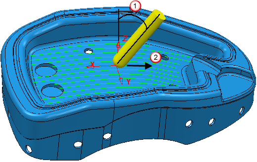
This example uses a constant Z toolpath with a Tool axis of:
Lead angle of 0
Lean angle of 0
Mode of Vertical.
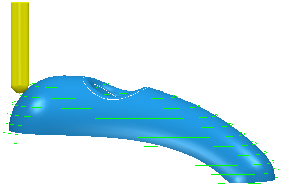
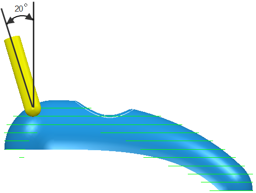
This example uses a constant Z toolpath with a Tool axis of:
Lead angle of 20
Lean angle of 0
Mode of Vertical.
-
Frame normal — This measures the lead angle from the normal to the preview frame. The preview frame is the pattern that is projected onto the solid model during toolpath calculation. This option is available only for the
Spine finishing strategy.
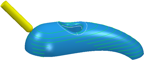
This example shows a toolpath with a Tool axis of:
Lead angle of 0
Lean angle of 0
Mode of Frame Normal.
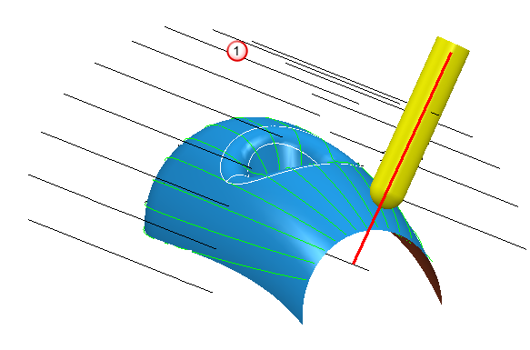 Preview frame
The tool is normal to the preview frame.
Fixed angle — Use the options in this section to fix the tool axis azimuth or elevation angle to a specified value after the orientation has been calculated using the selected Tool axis option. This fixes one rotational axis of a machine tool wherever possible, giving an improved surface finish and increases the overall feed rate by reducing acceleration and deceleration. The locked axis is overridden only to avoid a collision and to ensure the tool stays on the part.
-
Angle type
— Select the type of angle you are fixing:
Azimuth or
Elevation.
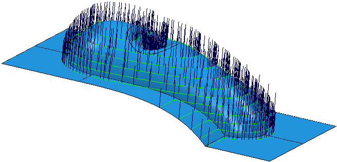
The effect of this option is visible when you select Solids > View > Draw Tool Axes.
A Tool axis of Vertical and a Fixed angle of None gives:
A Tool axis of Vertical and a Fixed elevation angle of 45
gives:
-
 Angle
— Enter the angle of the fixed tool axis.
Angle
— Enter the angle of the fixed tool axis.
- Coordinate system — Displays the coordinate system that PartMaker uses to set the fixed angle.