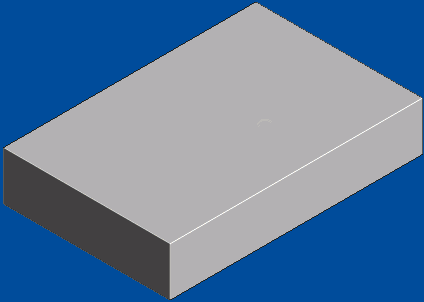
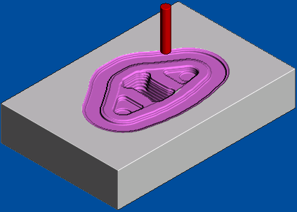
This example shows you how to visualise the stock removal whilst simulating a toolpath.
- Click Simulation tab and select the Toolpath (or NC Program) you want to simulate from the Simulation Path panel > Entity list.
- Select the Tool you want to simulate from the Simulation Path panel > Tool list.
The Tool option enables you to create a simulation with a tool other than the tool originally used to create the toolpath. For example, the tool tip could be exactly the same as the tool used to create the original toolpath, but have a tool shank and holder defined.
- Click View tab > Views panel > ISO > ISO 1 to set the view orientation.
- Click Simulation tab > ViewMill panel > Off to activate the simulation window, which initially shows a light grey block on the current background.

- Click Simulation tab > ViewMill panel > Shading > Rainbow.
If you simulate a toolpath or NC program using one view, you can change the view to another one when the simulation is complete. Typically, for speed you would simulate using the Simulation tab > ViewMill panel > Mode > Rotatable view and, on completion, change to the Simulation tab > ViewMill panel >Shading > Rainbow view.
- Click Simulation tab > Simulation Controls panel > Play > Play to End to start the simulation.
Click Simulation tab > Simulation Controls panel > Pause to pause the simulation.

- Repeat steps 1-6 to simulate additional toolpaths.
- To replay a simulation, you can:
- Rewind to the beginning by clicking Simulation tab > Simulation Controls panel > Go to Beginning, and then click Simulation tab > Simulation Controls panel > Play > Play to End.
- Select
Simulate from Start from the individual NC Program or Toolpath context menu, and then click Simulation tab > Simulation Controls panel > Play > Play to End.
The block is not reset but the toolpath is replayed.
- When the simulation is complete, click Simulation tab > ViewMill panel > Exit ViewMill to unload the simulation model.