Each machine tool can be described by its mathematical model, which is referred to as the Kinematic Model of the Machine. This model contains information used by the Autodesk Manufacturing Post Processor Utility to transform coordinates received from the CLDATA file (Model Coordinates) into coordinates of a machine tool (Machine Coordinates). This transformation is called the Inverse Kinematic Problem.
Solving this problem is one of the main tasks of the postprocessor and is more complex when handling multi-axis trajectories. To represent machine kinematics, Autodesk Manufacturing Post Processor Utility uses the Machine Tool Data Format, also called MTD-Format. Machine kinematics represented in this format are called MTD-Model. MTD-based machine kinematics representation is much more effective than the representation of kinematics by 3-axis, 4-axis and 5-axis classes, and also enables you to create programs for any configuration including 6-axis machines with 3 rotary axes.
The geometry of the machine can be defined either by a *.dmt triangle file defined in a CAD system or by parametric primitives (box and cone).
When creating your own MTD model, it is preferable to start from an existing MTD model and edit it.
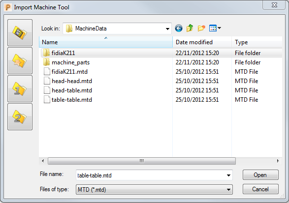
Clicking Machine Tool tab > File panel > Import displays all the existing MTD files:

For more information on how to improve collision checking, see Edit the .mtd file to improve collision checking.