This example shows you how to edit the orientation vectors of a tool axis using the Aerostructure.dgk model in the Examples folder.
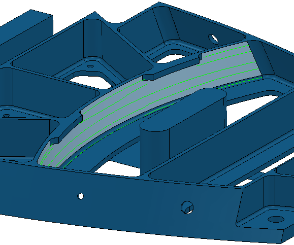
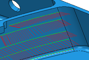
- Click Toolpath tab > Draw panel > Display > Orientation Normals to draw the orientation vectors on the active toolpath.
- Select the toolpath segment. The segment turns yellow.
- Click Toolpath Edit tab > Edit panel > Edit Within Region to display the Edit Toolpath Within Region dialog.
- On the Select Regions tab select a Define Region by of Whole Segments.
- On the Specify Changes tab:
- Select a Type of Editing of New Axis Definition.
This is the only option that you can use for editing orientation vectors.
- In the Tool Axis frame click
 . This displays the Tool Axis dialog.
- Select a Type of Editing of New Axis Definition.
- On the Machine axis control tab of the Tool Axis dialog:
- Select a Tool orientation type of Orientation vector.
- Select an Orientation vector of Fixed direction.
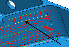
- In the Direction frame enter an Azimuth of 45.
- Click Accept.
- On the Edit Toolpath Within Region dialog, click Apply.
- On the Edit Toolpath Within Region dialog:
- Click Undo
 .
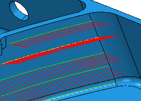
. - Enter a Blend Distance of 10.
- Click Apply.

- Click Undo