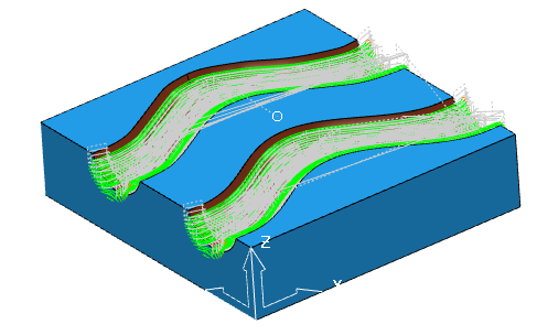
This example shows how to create and apply fixture offsets to toolpaths, using the Channels.dgk model in the Examples folder.
Create and add toolpaths to an NC program
- Before you can apply fixture offsets, you must create the relevant toolpaths to machine the channel:
- Roughing — Model area clearance toolpath using a tip radiused tool with a diameter of 15, a tip radius of 1, and a length of 75.
- Rest Roughing — Model rest area clearance toolpath using a ball nosed tool with a diameter of 15 and a length of 75.
- Steep and Shallow Finishing — Steep and shallow finishing toolpath using a ball nosed tool with a diameter of 10 and a length of 50.
- Create four identical toolpaths:
- In the Explorer, right-click the roughing toolpath and select Settings to display the Model Area Clearance dialog.
- On the dialog, click
 to create a copy of the toolpath.
 - Click Calculate.
- Without closing the dialog, click .
- Click Calculate.
This creates another copy of the toolpath. Repeat again, so you have four instances of the Roughing toolpath.
- Repeat step 1 to create four rest roughing toolpaths and four steep and shallow finishing toolpaths.
- Create an NC program.
- In the Explorer, right-click NC Programs and select Create NC Program.
This displays the NC Program dialog.
- In the NC Program dialog, enter the name: Channel with fixture offsets.
- Click Accept.
- In the Explorer, right-click NC Programs and select Create NC Program.
- In the Explorer, select all the toolpaths, right-click and select Add to > NC Program.
Create and apply fixture offsets
- Create the fixture offsets:
- On the NC Program dialog, select
 . This displays the Fixture Offset for NC Program dialog.
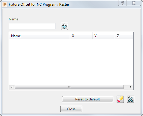
- In the Name field, enter G55 and click
 .
. - In the Fixture offset table, click in the X field and enter 300, then press Enter.
- On the NC Program dialog, select
- Repeat step 1 to create two more fixture offsets:
- G56 with a Y value of 300.
- G57 with an X value of 300 and a Y value of 300.
- Click Close.
- Apply the fixture offsets to the toolpaths in the NC program.
- On the NC Program dialog, click
 . This displays the toolpaths in the NC program toolpath table in the resizable Toolpath table window.
 - In the Toolpath table window, select Roughing_1 and then, on the NC Program dialog, select G55 from the Fixture offset list.
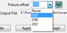
This applies the fixture offset G55 to the toolpath Roughing_1.
- On the NC Program dialog, click
- Select Roughing_1_1 and apply the fixture offset G56.
- Select Roughing_1_1_1 and apply the fixture offset G57.
- Repeat the process to apply the fixture offsets to the rest of the toolpaths.
Do not apply fixture offsets to the original toolpaths. Apply G55 to toolpaths ending in _1, G56 to toolpaths ending in _1_1, and G57 to toolpaths ending in _1_1_1.
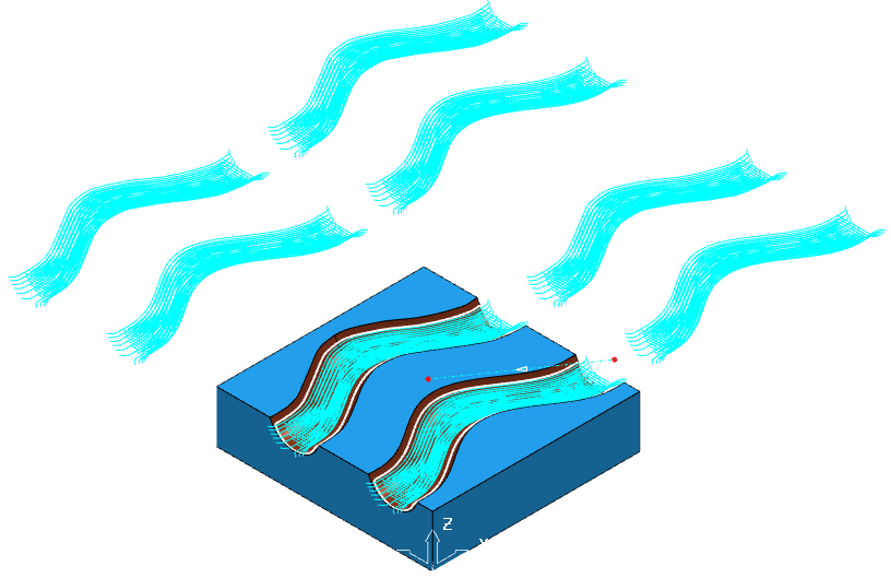
- On the NC Program dialog, click Apply.
- To display the toolpaths in their new positions, draw (
 ) the Channel with fixture offsets NC program.