This example shows you how to create a rib machining toolpath. This uses the Ribs_multi.dmt model in the Examples folder and a simple rectangular block.

In this example the ribs are far wider than in a typical ribbed model as this makes it easier to understand the process.
- Create a tapered spherical tool with:
- A Diameter of 25.
- A Tip radius of 7.
- A Taper angle of 25.
- A Length of 125.
- Click Home tab > Create Toolpaths panel > Toolpaths to display the Strategy Selector dialog.
- From the
Ribs category select
Rib Machining.
The Rib Machining dialog is displayed.
- Click the
Rib pattern
 button to display the
Rib Pattern Editor tab.
button to display the
Rib Pattern Editor tab.
This automatically changes the view to the view down the Z axis.
- Click Rib Pattern Editor tab > Create panel > Lines > Single Line.
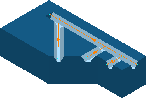
- Sketch the approximate centreline of the four channels as four lines.
For complete machining of each channel, the lines must extend beyond the open end of the channels. The direction of each line determines the machining direction. Because most rib machining tools break when plunging, it is best to start each line from the open end of the channel.

- If you cannot see the direction of the lines, click Rib Pattern Editor tab > Draw panel > Instrumentation.
- Click Rib Pattern Editor tab > Finish panel > Start Rib Surface Editor to display the Rib Surface Editor tab.
- Click Rib Surface Editor tab > Surfaces panel > Automatically Select to select all the wall and base surfaces of the channel.
- Click Rib Surface Editor tab > Finish panel > Accept. This closes the Rib Surface Editor tab and displays the Rib Machining dialog.
- On the
Rib Machining dialog:
- Select a Style of Rib walls.
- Enter a Max stepdown of 3.
- Click Calculate.
This creates the rib machining toolpath.
