The effects of the Tool Axis Direction Angle Limits are best seen by example. The following example uses Knob.dgk from the Examples folder.
- Create a Projection Surface Finishing toolpath with a Pattern Direction of V. Select the spherical surface and create the toolpath with a 10 mm Ball Nosed Tool and a Stepover of 5. Set the Tool Axis to Lead/Lean with Lead and Lean Angles of 0
 .
.
Don't close the Surface Projection Finishing dialog.
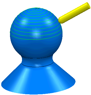
- Attach the tool to the toolpath (by selecting Simulate from Start from the individual Toolpath context menu), and then move the tool along the toolpath(using
 +CTRL+Shift), you can see the angle of the tool as it creates the toolpath. To see the shaded tool, select Shaded from the individual Tool context menu.
 - Click
 to create a copy of this toolpath.
 - On the strategy page, click
 to display the Tool Axis page and select the Tool axis limits option to display the Tool axis limits page.
 - On the Tool axis limits page:
- Select a Mode of Remove Toolpath.
- An Elevation Angle Start of 0, and an End of 90.
- In the graphics window, select the spherical surface and click Calculate on the Surface Projection Finishing dialog to recalculate the toolpath.
Only a portion of the toolpath is created (until the Elevation Angle limits are reached.)
- Repeat steps 3-5, but this time, on the Tool axis limits page, change the Mode to Move Tool Axis, and keep the Elevation Angle Start of 0 and End of 90.
- Recalculate the Surface Projection toolpath. You will see that more of the toolpath is created, but that the tool angle never exceeds the limits.

- Repeat steps 3-5, but now, change the Mode back to Remove Toolpath, and keep the Elevation Angle Start of 0 and End of 90.
- Change the Azimuth Angle to a Start of 180 and an End of 270. Recalculate the Surface Projection Finishing toolpath.
