Use the Turn bore roughing page to create a toolpath that rapidly bores a turning part.
Cycle — Select from:
- Turn — This cycle roughs within the defined material boundaries by feeding parallel to the part's centre line along the Z axis while stepping down in the X axis. If you select a Negative cut direction, the tool cuts from right to left. If you select a Positive cut direction, the tool cuts from left to right.
- Face — This cycle roughs within the defined material boundaries by feeding perpendicular to the part's centre line while stepping into the face of the part along the Z axis in the negative direction. If you select a Negative cut direction, the tool cuts down the X axis, from the top to centreline. If you select a Positive cut direction, the tool cuts up the X axis, from the centreline to the top.
- Back face — This cycle roughs within the defined material boundaries by feeding perpendicular to the part's centre line while stepping into the face of the part along the Z axis in the positive direction. If you select a Negative cut direction, the tool cuts down the X axis, from the top to centreline. If you select a Positive cut direction, the tool cuts up the X axis, from the centreline to the top.
Style — Select from:
-
Turning — Each roughing pass is cut in the same direction. For finishing, the tool traces the contour of the feature from right to left and is withdrawn from the part.
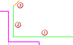
Roughing
Each roughing pass is cut in the same direction.

 Feed straight down into the part. The distance is based on the depth of cut.
 Cut down the right-hand wall.
 Feed straight across.
 Feed up the left-hand wall.
 Withdraw from the wall, retract all the way across the feature.
Finishing

 The tool traces the contour of the feature from right-to left.
 The tool is withdrawn from the part based on the Lead out angle and the Lead out distance.
 -
Two-way — Roughing with two-way grooving tools is bi-directional. The two-way finishing style is performed using a unique strategy that is enabled by having a grooving tool that cuts in both directions.

 Feed straight down into the part. The distance is based on the depth of cut.
 Feed straight over in Z.
 Withdraw away from the wall and rapid back slightly in Z.
 Feed straight down again based on the depth of cut.
 Feed straight in the -Z direction.
 -
Round insert — Round insert tool finish toolpaths are the same as Turning finish toolpaths. They are designed to ease the tool more gently into a groove shape. When selected the Round insert page is available.
Round tool roughing toolpaths are designed to ease the tool more gently into a groove shape through an engage angle. A round tool is required and you must manually select the tool for this toolpath type.

Tolerance — Enter a value to determine how accurately the toolpath follows the contours of the model.
Below centreline — Select this option to make the tool work on the negative X side of the turning centreline.
Cut direction — Select an option to specify the cutting direction of the tool:
-
Positive — The tool cuts in the positive direction of the cutting axis, which depends on the selected Cycle.
- Turn — The tool cuts in the +Z direction.
- Face — The tool cuts in the +X direction.
- Backface — The tool cuts in the +X direction.
-
Negative — The tool cuts in the negative direction of the cutting axis, which depends on the selected Cycle.
- Turn — The tool cuts in the -Z direction.
- Face — The tool cuts in the -X direction.
- Backface — The tool cuts in the -X direction.
Thickness — Enter the amount of material to be left on the part. Click the
Thickness
 button to separate the
Thickness
box in to
Radial thickness
 Axial thickness
 . Use these to specify separate
Radial and
Axial thickness as independent values. Separate
Radial and
Axial thickness values are useful for orthogonal parts. You can use independent thickness on sloping walled parts, although it is more difficult to predict the results.
 Radial thickness — Enter the radial offset to the tool. When 2.5-axis or 3-axis machining, a positive value leaves material on vertical walls.

 Axial thickness — Enter the offset to the tool, in the tool axis direction only. When 2.5-axis or 3-axis machining, a positive value leaves material on horizontal faces.

Depth of cut — Enter a step increment for each pass that the roughing routine performs on the part. The interpretation of Depth of cut depends on whether Constant depth of cut is selected.
If Constant depth of cut is deselected, the Depth of cut value you set is the maximum depth of cut for the feature. If the Depth of cut evenly divides the depth of your feature, your increment is used. If it results in a final pass that is quite shallow, the Depth of cut is adjusted to result in even roughing passes. For example if you have a feature that is 0.5 mm deep and specify a Depth of cut of 0.4, the feature is roughed in two even passes 0.25 mm deep instead of one pass of depth 0.4 mm and another pass with depth of 0.1 mm.
If Constant depth of cut is selected, the feature is cut using this depth for each pass.
- Maximum — Enter the maximum depth of cut.
- Constant depth of cut — See Depth of cut.
Profile pass — Select an option to specify whether a wall pass is inserted into the toolpath.
This attribute applies to turning and boring roughing strategies. Select:
-
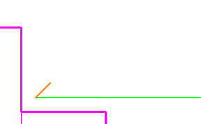
Always to perform all three moves of a typical roughing pass:
- Move straight across the part
 .
. - Move up the wall to remove any scallops
 .
. - Withdraw from the part at an angle
 .
.

- Move straight across the part
-
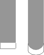
Skip all to omit the second move. Select this option when using a tool that does not cut upwards well. For example:

- Skip number to choose how many passes are skipped. For example, select 1, to skip the wall move for the first roughing pass but not for subsequent passes. This option is only available for boring strategies.
Deburring — Select to automatically insert arc moves on outside corners.

 — Deburring on.
 — Deburring off.
The effects of deburring are:
- Wasted motion by the machine is minimised; however the posted part program may be slightly longer in the number of blocks used.
- Burrs are removed, but otherwise the part has the same shape and dimensions given by the feature curve because the radius of the inserted arc is the same as the tool nose radius.
- Machine motion is smoother.
Undercuts — Select an option to specify how the toolpath considers undercuts.