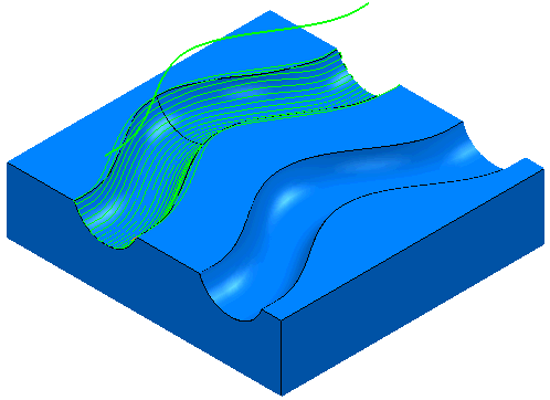
This strategy is similar to the Line Projection Finishing strategy except that the pattern is a curve rather than a line. It is a technique that can be used when the surface definition isn't adequate to provide good results when using surface projection finishing.
This uses the channels.dgk model in the Examples folder.
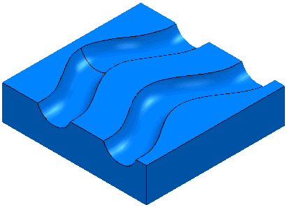
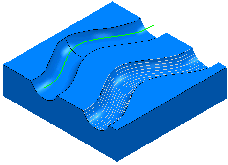
It consists of two channels. One has a well-defined surface the other, two poorly defined surfaces.
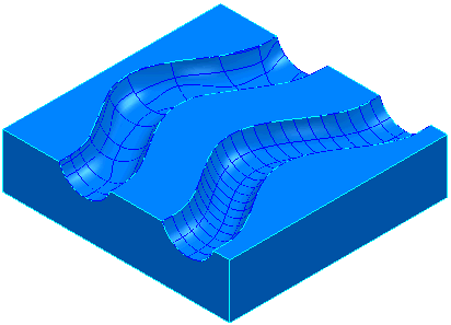
Surface projection works well on the well-defined surface and badly on the poorly defined surfaces.
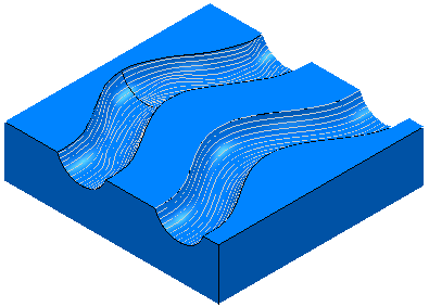
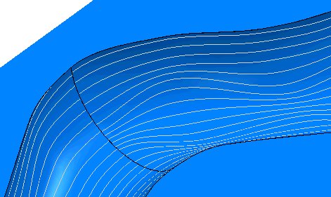
If you look in detail at the back channel you can see the problem:
Curve projection Finishing can be used to solve this problem. You need a Pattern to define the locus of the toolpath. In this case a pattern called Spine.dgk (in the Examples\Patterns directory) going through the centre of the channel.
- Click Home tab > Create Toolpaths panel > Toolpaths to display the Strategy Selector dialog.
- From the
Finishing category select
Projection Curve Finishing.
On the Curve projection page:
- Select a Pattern of Spine.
- Select a Style of Linear.
- Select a Direction of Outwards.
- Enter an Angular Stepover of 10.
- On the
Pattern page:
- Enter an Azimuth Angle Start of -90.
- Enter an Azimuth Angle End of 90.
- Click Apply.
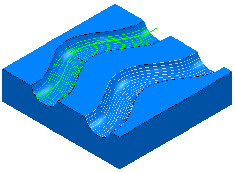
This produces the required smooth toolpath. Looking in detail:
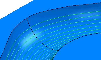
- If you offset the spine up the Z axis you can get a more complete toolpath in the channel.
