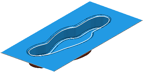
This example shows you how to limit a toolpath to a boundary. You can use this technique to contain the tool within a specific area. This can be used to keep the tool clear of any clamps or obstacles.
- Open the
DeepFlatMould.dgk model in the
Examples folder and create a block, tool and
Shallow Boundary.
- Delete the outer two contours by selecting them and pressing the
Del key.
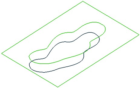
- Create a Model Area Clearance toolpath within the boundary.
- You can see that only the cavity is machined.

The links are also contained within the boundary. Boundaries limit the tool centre. If you create another toolpath with a different tool you will need to create a new boundary, unless you use the Limit > Tool Periphery option on the Area Clearance dialog. This option enables you to create one boundary and use it for all tools.
You can also use this technique to limit all approach moves, as well as cutting moves, to within a specific area.
- Create a
Block Boundary.

- Click Boundary tab > Edit panel > Curve Editor to display the Curve Editor tab.
- Click Edit tab > Edit panel > Transformations > Offset to display the Offset toolbar.
- On the
Offset toolbar:
- From the
Offset type
 flyout click the
2D round
flyout click the
2D round
 button.
- Enter a Distance of 10.

The boundary is offset by 10mm.
- From the
Offset type
- You can create area clearance toolpaths using this boundary where the toolpath plus all approach moves are contained within this boundary.