Use the Direction dialog to edit the direction of an item. A direction is defined in terms of a unit vector.
Click  on appropriate dialogs to display the Direction dialog.
You can also use the X Axis Direction, Y Axis Direction, or Z Axis Direction options on the Workplane Editor tab to display the Direction dialog.
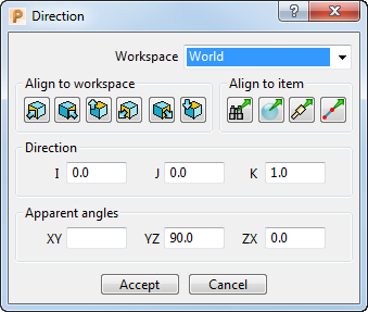
This tab contains the following:
Workspace — Select which workspace you are working in.
- World — Specifies the point relative to the global coordinate system.
- Workplane — Specifies the point relative to the active workplane. This option is available only when there is an active workplane and you are editing a non-active workplane.
Align to workspace — Select an axis (of the global coordinate system) to align to the selected workspace. Choose from:
 positive X-axis.
 positive Y-axis.
 positive Z-axis.
 negative X-axis.
 negative Y-axis.
 negative Z-axis.
For example, if you start with this:
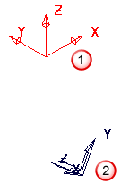
 The workplane that you are editing.
 The active workplane (or the global coordinate system if there is no active workplane).
- Click Workplane Editor tab > Edit panel > X Axis Direction.
- In the Direction dialog click . The workplane changes to:
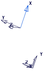
The X axis of the workplane is aligned with the Y axis of the global coordinate system.
- In the Direction dialog click . The workplane changes to:
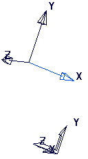
The X axis of the workplane is aligned with the -Z axis of the global coordinate system.
Align to item — Select an option to determine the direction vector of the item.
 Align with view — Click to align the direction vector with the current graphics view.
 Align with geometry — Click to align the direction vector so it is normal to the surface at that point.
 Align with tool — Click to align the direction vector so it is aligned with the tool axis.
 Align with a line — Click to align the direction vector to a user-defined line.
Direction — Enter the I, J, and K coordinates for the unit vector.
Apparent angles — Displays the apparent angle of the unit vector from the XY, YX and ZX plane of the selected Workspace.