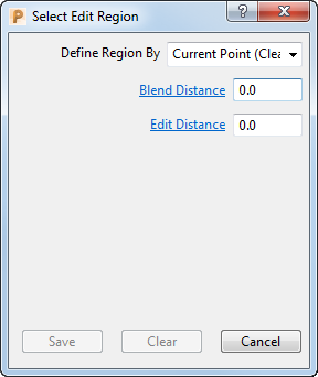
The Select Edit Region dialog enables you to specify the area of a toolpath you want to edit.
Click Dynamic Machine Control tab > Edit panel > Select regions to display the dialog.

The options on the dialog vary depending on your selection from the Define Region By list.
The common options are:
-
Define Region By — Specifies how regions of the toolpath are selected.
- Plane — Selects regions of the toolpath that lie to one side of the specified plane.
- Boundary — Selects regions of the toolpath that lie to one side of a specified Boundary.
- Polygon — Selects the regions of the toolpath that lie to one side of a user-defined polygon. Click in the graphics window to draw the polygon.
- Whole Segments — Selects complete segments of the toolpath.
- Pairs of Points — Selects the region of the toolpath between two specified points. Click on a toolpath to insert a point.
- Current Point — Selects a point on the toolpath.
- Blend Distance — Enter a value to specify the distance over which the tool axis changes from the new orientation to the original. This can minimise marks on the model caused by a sudden change in tool axis.
-
Side — Determines which side of the plane, polygon, or boundary is selected.
- Inner — Selects the inside region.
- Outer — Selects the outside region.
- Save — Saves the selected portions of the toolpath, and adds it to any other portions of the toolpath that have already been saved.
- Clear — Removes all portions of the toolpath from the saved selection.
The unique options are:
Plane
-
Type — Specifies the limiting plane.
- Plane X — Select to specify the YZ plane. Either pick a point in the graphics window or enter the X coordinate in the Point frame of the dialog.
- Plane Y — Select to specify the ZX Plane. Either pick a point in the graphics window or enter the Y coordinate in the Point frame of the dialog.
- Plane Z — Select to specify the XY plane. Either pick a point in the graphics window or enter the Z coordinate in the Point frame of the dialog.
- Arbitrary — Select to either pick two points on the screen using the left mouse button to define the normal to the required plane, or enter X, Y, and Z coordinates in the Point and Normal areas of the dialog.
- Point — Enter values to specify the origin of the plane.
- Normal — The fields display the direction of the normal of the plane.
Boundary
- Boundary — Select the boundary to limit the toolpath.
- Projection Plane — Select the plane in which the toolpath is limited.
Current Point
- Edit Distance — Enter a value to specify the distance either side of the selected point to apply the tool-axis edit.