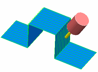
This simple example uses a raster toolpath over a step to show the effect of collision avoidance.

When you create a simple raster toolpath over this, there are collisions between the step and the shank:

One way round this is to increase the length of the tool. Another way is to change the toolpath strategy.
The third way is to use collision avoidance. In this case, the initial Tool Axis is Vertical.
- Select Automatic Collision Avoidance.
- Select the Collision Avoidance tab.
- Enter a Tool Tilt Axis of Lead, a Shank Clearance of 1.0 and a Holder Clearance of 1.0.
- Click Accept.
- Create a new raster toolpath.
You can see that the toolpath now tilts on the steep portions to avoid the tool holder colliding.
It is still 3-axis toolpath on the flat portions where the tool holder does not collide:
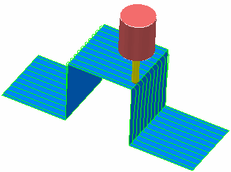
In summary, the tool tries to respect the original Tool Axis Definition for as much of the toolpath as possible. Only when this is not possible does the tool axis change, in the direction specified in the Tool Tilt Axis field, until the tool assembly no longer collides.