This example shows you how to create a flowline toolpath. It uses the 5axisModel.dgk in the Examples folder with a block and a 5 mm ball nosed tool.

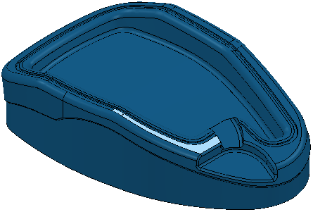
- Select the two highlighted surfaces.

- Click Pattern tab > Create panel > Pattern.
- Click Pattern tab > Edit panel > Insert > Model.

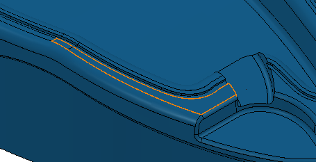
This creates an embedded pattern at the edge of the selected surfaces.
- The pattern currently contains one curve and must be broken into four curves. Click Pattern tab > Edit panel > Curve Editor to display the Curve Editor tab.
- Click Edit tab >Edit panel > Segment > Cut.
- Select the curve where you want to cut it. The cursor changes to a knife and the curve turns yellow.

- Click the curve again to cut it into two distinct curves.

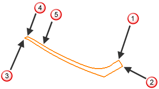
This breaks the curve at
 .
.

- Repeat steps 7 and 8 to break the curve at
 ,
,
 , and
, and
 .
.
- The pattern is still split at
 . To merge the two segments, select the two segments.

- Click Edit tab > Edit panel > Segment > Merge.
A PowerMill information dialog states Geometry reduced from 5 to 4 pieces. 0 Closed, 4 Open. Reduced selected curves from 2 to 1.
- Click OK to close the PowerMill information dialog.
- Click Edit tab > Finish panel > Accept to apply the changes and close the
Curve Editor tab.

- Click Home tab > Create Toolpaths panel > Toolpaths to display the Strategy Selector dialog.
- From the
Finishing category, select the
Flowline finishing strategy, then:
- Select the embedded pattern.
The Status is Valid and the pattern changes colour. If this is not the case, see Defining the flowline curves.

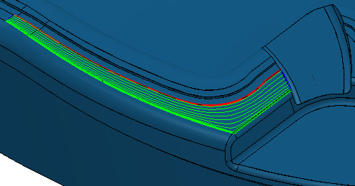
The green curve is the start drive curve. the red curve is the end drive curve, and the blue curves are the limit curves.
- Enter a Stepover of 3.
- Click
Calculate.

- Select the embedded pattern.