Use this dialog to specify how to draw the model.
Click the dialog launcher button
 on the View tab > Appearance panel to display the
Model Drawing Options dialog.
This dialog contains the following:
Wireframe
-
Style — Select the line display of the wireframe. Choose from the following:
- Solid — Displays the wireframe as a solid line. This is the default option.
- Dashed — Displays the wireframe as a dashed line.
- Chained — Displays the wireframe as a chained line (dot dashed line).
When you select a line Style for the wireframe, the View tab > Appearance panel > Wireframe option toggles between the selected style and not displaying the wireframe.
-
Colour — Click
 to display the
Select Colour dialog where you can choose the colour of the wireframe.
 displays the currently selected colour.
-
Laterals — When selected, draws the laterals of a feature or a surface.
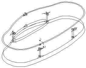
-
Longitudinals — When selected, draws the longitudinals of a feature or a surface.
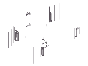
With both the Laterals and the Longitudinals selected, you see the complete feature or surface.
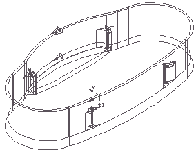
-
Filter Angle — Enter the filter angle. In most cases the default value of
20
 is acceptable. In some cases
Stl and
ttr
formats produce better wireframe representation by modification of the wireframe angle filter. Experiment with this filter to produce the best result for a particular model. A smaller value produces more boundaries and a larger value produces fewer. You generally need a smaller value if your model consists mainly of smooth surfaces. This value has no impact on the type of wireframe generated for triangles (*.tri and
*.dmt files).
Shade
-
Shade Inside — When selected, shades the underside of the model red.
Shade Inside is the default setting.
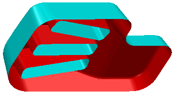
-
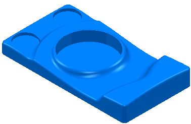
Draw Outlines — When selected, the edge curves of surfaces are black. This is visible only if the wireframe is not drawn.
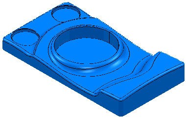
When deselected, edge curves of surfaces are drawn in the surface colour.
-
Shade Colour — Click to specify the colour of the plain shaded model (the colour of the model when you select View tab > Appearance panel > Shade > Plain). The currently selected colour is displayed next to the
Shade Colour
 field. To change the colour, click
 to display the
Select Colour dialog.
- Shading Tolerance — Enter the shading tolerance. The finer the tolerance, the smoother the shading, but the rendering time increases. This tolerance is a visual tolerance and does not affect the machining tolerance.
- Draft Angle — Enter the draft angle. This is an angle incorporated into a wall of a mold, so the opening of the cavity is wider than the base, which allows for easier ejection of the part. When selecting View tab > Appearance panel > Shade > Draft Angle, anything less than this value is red.
-
Warning Angle — Enter the warning angle. This must be larger than the draft angle and warns you that you are approaching the draft angle. When selecting View tab > Appearance panel > Shade > Draft Angle, anything less than this value but larger than the
Draft Angle is shaded yellow.
In the case with a Draft Angle of 5
 and a
Warning Angle of 20
 , then anything less than 5
 is shaded red, anything between 5
 and 25
 is shaded yellow, and anything above 25
 is shaded green.
- Minimum Tool Radius — Enter the radius used when selecting View tab > Appearance panel > Shade > Minimum Radius. Anything less than this value is shaded red.