Use the Fixed Angle area, on the Definition tab of the Tool Axis dialog, to fix the azimuth or elevation angle of the tool.
-
Fixed angle —Select whether you are fixing the
Azimuth or
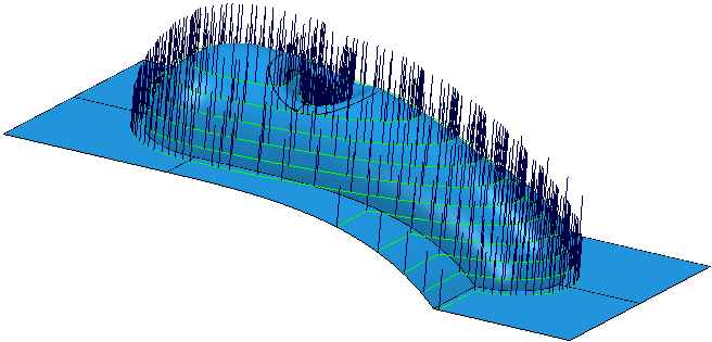
Elevation angle. The effect of this option is visible when you select Toolpath tab > Draw panel > Display > Tool Axes.
A Tool axis of Vertical and a Fixed Angle of None gives:

A Tool axis of Vertical and a Fixed Angle of Elevation set to 45
 gives:

-
 Angle
— Enter the angle of the fixed tool axis.
Note: Automatic collision avoidance and tool axis limits can override the angle specified here.
-
Rotary axis configuration — The read-only field displays the coordinate system
PowerMill uses to fix the tool axis angle, if a
Fixed Angle of
Azimuth or
Elevation is selected. To specify which workplane
PowerMill uses, select a rotary-axis-configuration option on the
Machine tool page of a strategy dialog. The effect of this option is visible when you select Toolpath tab > Draw panel > Display > Tool Axes.
- Select a Tool axis of Vertical.
- From the Fixed Angle list, select Elevation.
- In the
Fixed Angle box, enter 0
 . This produces:
- Select a Tool axis of Vertical.
- From the Fixed Angle list, select Elevation.
- In the
Fixed Angle box, enter 0
 .
.
- On the
Machine tool page, from the
Rotary axis configuration area, select
Override toolpath workplane. Then select a workplane created by rotating by 30
 about the X axis. This produces:
In this instance, part of the toolpath is removed as otherwise the tool would gouge the part.
When you use a
Tool Axis of
Vertical the azimuth is undefined. However, to fix the elevation an azimuth is needed. In this instance, the azimuth is defined as 90 from the direction of travel. Other
Tool Axis types have a defined azimuth.