This example shows you how to create a gauge distance offset. It simulates the effect of having a tool holder without having one defined. This is useful when performing a machine tool simulation, as the machine tool mounts the tool (and holder) at the tool attachment point.
- Click Machine Tool tab > File panel > Import to load the machine tool.
- Click Simulation tab and select the Toolpath (or NC Program) you want to simulate from the Simulation Path panel > Entity list.
- Select the Tool you want to simulate from the Simulation Path panel > Tool list.
The Tool option enables you to create a simulation with a tool other than the tool originally used to create the toolpath. For example, the tool tip could be exactly the same as the tool used to create the original toolpath, but have a tool shank and holder defined.
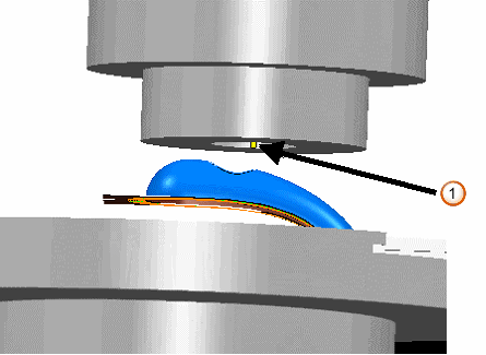
If you do not define a holder, only the tool is displayed:

 — Tool
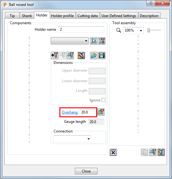
 - To simulate the effect of having a holder defined you must edit the tool definition. From the individual tool context menu, select Settings and then select the Holder tab.

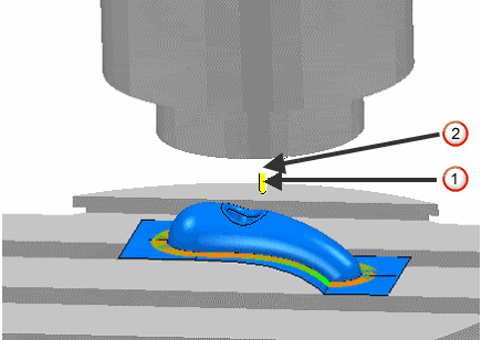
- Enter an Overhang value equivalent to the holder length. This defines the length of tool protruding from the gauge face of the machine.Then click the Close button. This displays the tool and the overhang.

 — Tool
 — Overhang
Note: In this way, the Overhang field on the Holder tab of the Tool dialog is used as a Gauge Distance Offset value in machine tool simulation.