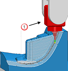
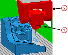
This example shows how to use the functions of dynamic machine control to prevent collisions between the machine tool and the workpiece.
The example uses the DynamicMachineControl_Example project in the Examples folder.
- In the Toolpaths branch of the Explorer, right-click the toolpath and select Simulate from Start.
As the machine tool machines down the surfaces of the workpiece, the head and the A axis-component of the machine tool collide with the workpiece.


- Click Toolpath Edit tab > Edit panel > Dynamic Machine Control to display the Dynamic Machine Control tab.
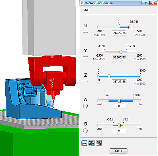
- Click Dynamic Machine Control tab > Settings panel > Machine Tool Position to display the Machine Tool Position dialog.
The dialog displays the position of each machine tool axis. Displaying the dialog is useful because it enables you to see the movement of the axes and, in particular, if you move an axis beyond its limit.

- Specify the increment values of the rotary axes of the actual machine tool. This ensures that any adjustments you make to the virtual machine tool's axes can be achieved by the actual machine tool.
- Click Dynamic Machine Control tab > Settings panel > Settings to display the Dynamic machine control dialog, and select the Axis restrictions tab.
- For both A and B axes, select the Restrict axis option and specify an increment value of 2.
- Reconfigure the machine tool's position and tool axis.
- Click Dynamic Machine Control tab > Tool Axis Controls panel > Machine Tool Graphics to display the grab-handles aligned to the axes of the machine tool.
- Use the grab-handles to reconfigure the machine tool.
- Click Dynamic Machine Control tab > Utilities panel > Swap Configuration to swap the machine tool's configuration. PowerMill improves the machine tool's clearance by adjusting the configuration of the machine tool (in particular by rotating the machine head by 180 degrees) but without altering the tool axis.
- Double-click on various areas of the toolpath to make sure the new configuration and tool axis do not cause any new collisions.
- Click Dynamic Machine Control tab > Edit panel > Update Toolpath to update the machine tool's new position and tool axis.
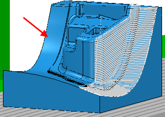
- The left side of the workpiece requires a similar toolpath. Repeat step five to achieve a suitable machine tool position and tool axis.

- Click Dynamic Machine Control tab > Utilities > Create Workplane > Aligned with Tool to create a workplane aligned with the tool. You can use this workplane when you create the toolpath for the area.
- Click Dynamic Machine Control tab > Finish panel > Accept to accept the changes.