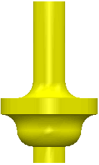
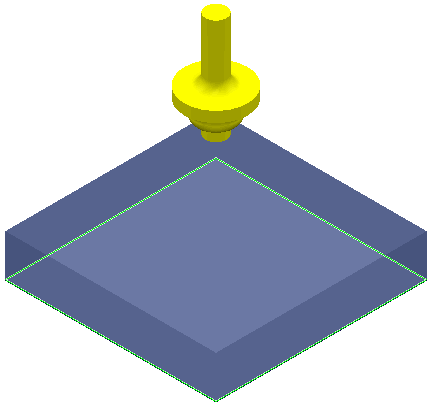
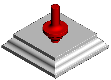
This example shows you how to create a routing tool.
- Click Home tab > Tool panel > Create Tool > Routing.
- Click
Load tool profile
 , and navigate to the directory where your tool profile is stored. For this example, use
Tool_Routing.dgk from the
Examples directory.

- Click Home tab > Setup panel > Block > Block and create a block with dimensions:
Min X — 0, Max X —100
Min Y —0, Max Y —100
Min Z —0, Max Z —20
- Click
Accept on the
Block dialog.
Do not Calculate the block.
- Click Model tab > Create panel > Plane > From Block, and then enter a Z Limit for the plane. For this example, enter 0.
- Click Pattern tab > Create panel > Pattern to create a new pattern.
- Click Pattern tab > Edit panel >Insert > Model to insert the model into the active pattern.
- Click Home tab > Create Toolpaths panel > Toolpaths to display the
Strategy Selector dialog, and select
Finishing category >
Pattern Finishing.
- On the Tool page, select the routing tool you created.
- On the Pattern finishing page, in the Drive curve area, select the pattern you just created.
- Click Calculate.

Simulate the toolpath to see the effect of the routing tool.
- Click Simulation tab > ViewMill panel > Off/On to enable ViewMill.
- Select the
Pattern Finishing toolpath
 you created from the Simulation tab > Simulation Path panel.
- Click Simulation tab > Simulation Controls > Play to start the simulation.
