A clamping workplane gives you the ability to specify limits relative to a particular workplane. If you are generating a toolpath in one workplane (A), and the machine limits are available in another (B), then it is easier to specify the limits by making B the clamping workplane.
This example looks at a toolpath limited by the Tool Axis Limits and uses a Clamping Workplane. It uses Knob.dgk from the Examples directory, rotated through 270 in Y.
in Y.
 workplane, but the machine limits are available in the
  workplane.
- From the individual Model context menu, select Edit >Transform to display the Transform Model dialog.
- In the Transform Model dialog, Rotate the model 270 in Y and click Accept.
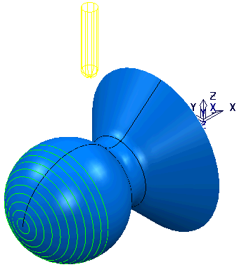
- Create a Projection Surface Finishing toolpath with a Pattern Direction of V. Select the spherical surface and create the toolpath with a 10 mm Ball Nosed Tool and a Stepover of 5. Set the Tool Axis to Lead/Lean with Lead and Lean Angles of 0.
- Click
 to create a copy of this toolpath.
 - On the strategy page, click
 to display the Tool Axis page and select the Tool axis limits option to display the Tool axis limits page.
 - On the Tool axis limits page:
- Select a Mode of Remove Toolpath.
- An Elevation Angle Start of 0, and an End of 90.
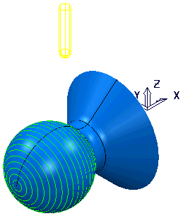
- In the graphics window, select the spherical surface and click Calculate on the Surface Projection Finishing dialog to recalculate the toolpath.
Only a portion of the toolpath is created (until the Elevation Angle limits are reached.)
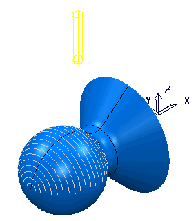
However, this is not what is required, as the machine limits are not defined in the correct workplane. Therefore you need to create a workplane rotated around Y by 270
. - From the Workplanes context menu, select Create Workplane. This displays the Workplane Editor tab.
- Click Workplane Editor tab > Edit panel > Twist around Y to display the Twist dialog.
- Enter an Angle of 270 and click Accept.
- Click Workplane Editor tab > Finish panel > Accept to accept changes and close the tab.
- Repeat steps 2-4, but this time, on the Tool axis limits page, select the Workplane you just created.
Leave the other parameters unchanged and ensure that the new workplane is not active.
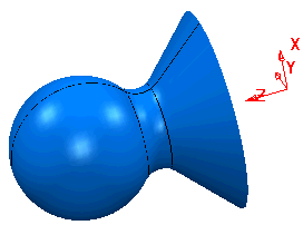
- Select the spherical surface on the model and recalculate the Projection Surface Finishing toolpath.