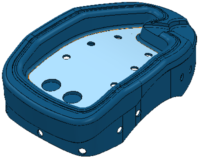
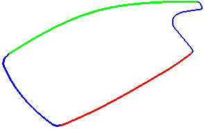
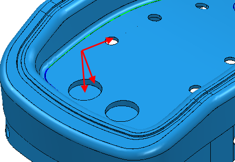
When creating flowline toolpaths the area inside the embedded pattern is machined. However, if you have holes in the model, this area may not be what you expect. This example uses the 5axis_with_holes.dgk model in the Examples folder with a block and a 5 mm ball nosed tool.

To create a flowline toolpath on the selected surface:
- Click Home tab > Create Toolpaths panel > Toolpaths to display the Strategy Selector dialog.
- From the Finishing category select Flowline Finishing.
- On the
Flowline finishing page:
- Select the embedded pattern.
- The Status is Valid and the pattern changes colour.

However, if you now try to Calculate this toolpath you will not get your required toolpath. PowerMill creates a toolpath on all surfaces inside this pattern. So the surfaces in the holes are also considered.

Since these surfaces have other surfaces next to them, they are also considered.

This is repeated over the whole model.
To avoid this problem, the cylindrical surfaces must be ignored when machining.
- Create a batch flowline toolpath by defining the curves and then click OK.
- Select all the cylindrical surfaces.
- Click Home tab > Setup panel > Thickness to display the Thickness Preferences dialog.
- Select the
Surfaces tab and select the top thickness set. Then:
- Select a Machining Mode of Collision.
- Click
Acquire Components
 .
.
- Click Apply.
- Click Accept.
- Click View tab > Appearance panel > Shade > Toolpath Machining Mode.
The components that have a Machining Mode of Collision are yellow.

- From the individual Toolpath context menu, select Settings.
- Click
Calculate.
