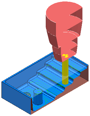
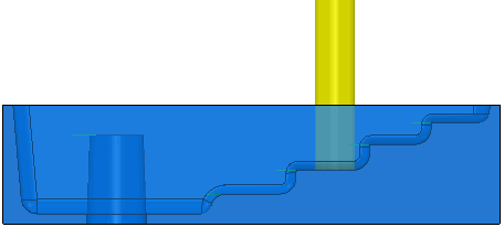
This example shows to how to use Dynamic Sectioning to analyse a toolpath using the Flats.dgk model in the Examples folder. The toolpath used in the example is an area clearance toolpath with Machine Flats set to Area. The tool is at an area of interest on the toolpath.
Tip: To arrive at an area of interest on the toolpath, use the
Simulate from Start option from the individual toolpath context menu and step through the toolpath using the controls on the
Simulation tab.
- From the Graphics context menu select Dynamic Sectioning. This displays the Dynamic Sectioning dialog.
- Change the Axis to Y so that the sectioning is done normal to the Y axis of the global transform (as there is no active workplane).
- Select
Back Plane and move the slider above this option to display a dynamic section of the model. As you move the slider, the displayed model is cut away to reveal more details. Select
Front Plane if you want to view the cut section from the front of the model.

You can change your view to see the position of the tool on the model more clearly.
In certain cases, Dynamic Sectioning offers a much clearer result than a translucent view (using the Translucency option available from the individual model context menu) of the model.
For example, compare the clarity of a dynamically sectioned view of the project with a translucent view of the same project:
Dynamic section view:

Translucent view:
