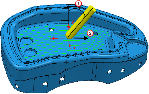
The tool is at a fixed angle relative to the local normal to the pattern frame (this is the preview frame visible when you click the Preview button on a finishing dialog). The local normal is going to vary as you go along the pattern, at each point of the pattern and relative to the direction of the pattern at each point.
You can specify two different angles - Lead and Lean. If you specify both a Lead and a Lean angle, the Lead Angle is applied first in the direction of the move, and then the Lean Angle is applied from this rotated position towards a vector perpendicular to the move.
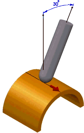
Lead Angle — Enter the angle of the tool axis in the direction of travel. It is measured from the perpendicular to the direction of travel. 0 is vertical. Typically, this is used to avoid cutting at the centre of a ball nosed tool on flattish areas. A typical Lead Angle is 15.
 Lead angle, which is in the direction of travel. In this example the angle is in the ZX plane.
 Direction of travel.
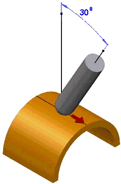
Lean Angle — Enter the angle of the tool axis at right angles to the direction of travel. 0 is vertical. Typically, a Lean Angle is used to avoid the tool holder colliding with the part, to avoid collisions caused by a step, or to allow you to use a smaller tool when machining up to a step.

Lean angle, which is perpendicular to the direction of travel. In this example the angle is in the YZ plane.
Direction of travel.