To specify advanced creation options when creating a surface using the Network over triangles option, click Advanced on the Smart Surfacer to display the Network of Wireframe Over Triangles Options dialog:
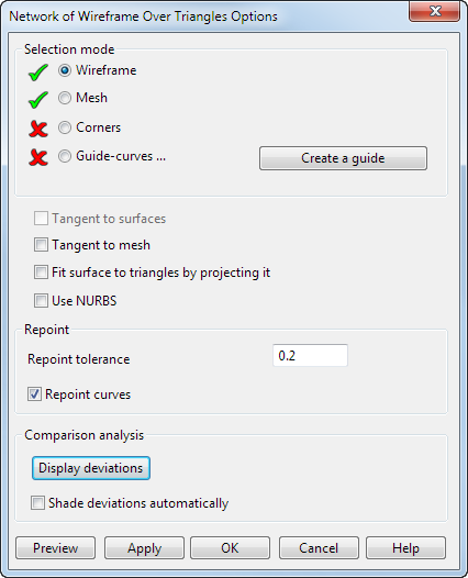
Use the options on the dialog as described below:
- Select the following on your model:
- Wireframe
- Mesh
- Corners (optional)
- Guide curves (optional)
Use Corners and Guide curves to help define the shape of the surface.
- Select the following options as appropriate:
- Tangent to surface to create the surface tangent to the surrounding surfaces on which the selected curves are dependent.
- Tangent to mesh to create the surface tangent to the mesh.
-
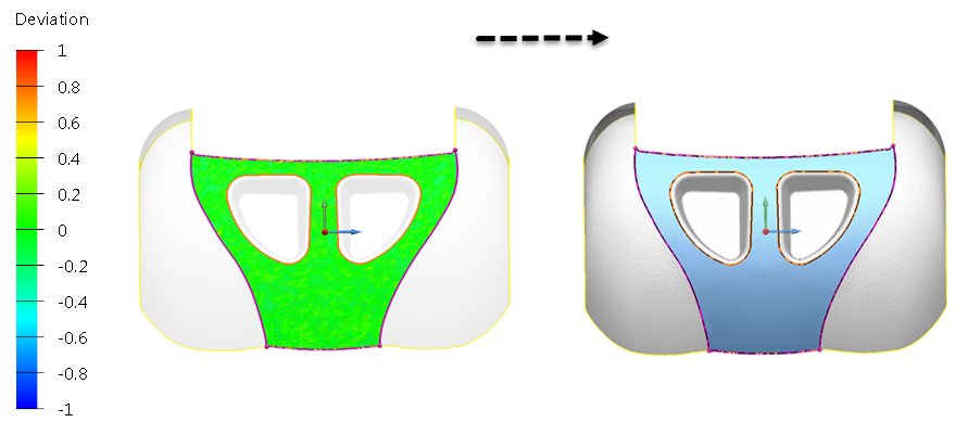
Fit surface to triangles by projecting it. Use this option to project the surface to the curve as shown in the following example:
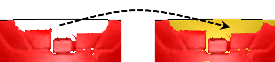
Selecting this option is useful when a mesh contains a damaged edge. It uses a curve that bridges the gap in the damaged mesh, where there are missing triangles. When the surface is created, this option causes the surface to be projected to the curve that was created.
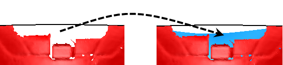
If the option is deselected (default), the edge of the surface is matched to the damaged edge of the mesh, as shown above.
- Use NURBs to create a NURB surface instead of a power surface.
- Enter Repoint tolerance.
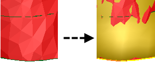
- Deselect Repoint curves to produce a surface that closely matches the triangles, including any triangles that might contain errors. In the example below, this produces an unsmooth surface that is almost identical to the mesh.
Selecting Repoint curves is recommended if the curves have a lot of randomly distributed points. Repointing the curves will produce a smoother surface, as shown below:
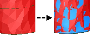
The following diagram shows the surface construction that result from the two options:
 With Repoint curves deselected, all the internal surface curves are displayed.
 With Repoint curves selected, the surface curves are evenly distributed as the result of repointing.
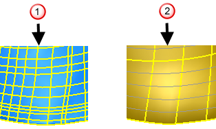 Note: Repointing can alter the shape of the curve so that the surface may deviate from the original geometry.
 - Click Hide deviations to display the model without the colour map.
If the colour map is not displayed, click Display deviations to show the deviations and the colour map.
- Shade deviations automatically is deselected by default. Select this option to change the default setting when the dialog is next displayed.
- Click Preview to see the results. If necessary, make changes and click Preview.
- Click Apply to create the surface. The dialog continues to be displayed. Create additional surfaces as required.
- When all the surfaces have been created, click OK. To cancel the creation of all the surfaces, click Cancel.