Create holes in the mold plate, and position them by creating layout piece lines:
- Select either the
Continuous
Line
 or the
Single
or the
Single
 line
— Lets you create continuous lines on the mold plate. Continuous lines are ones where the end of the last line becomes the start of the next.
— Lets you create single lines. These lines are created between two distinct positions.
line
— Lets you create continuous lines on the mold plate. Continuous lines are ones where the end of the last line becomes the start of the next.
— Lets you create single lines. These lines are created between two distinct positions.
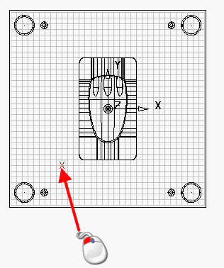
- Enter a position on the grid.
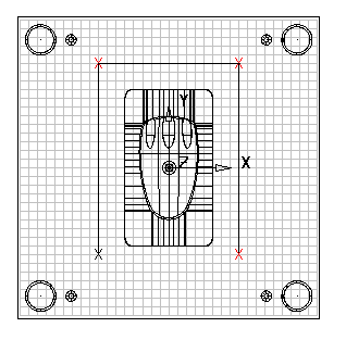
- Enter all the positions for the lines. Use the following buttons on the
Sketch the desired flow of coolant
page to help you create the layout.
 — Selects and deselects the
Snap to grid function. This option is selectedby default.
— Selects and deselects the
Snap to grid function. This option is selectedby default.
 — Click the
Show outline button to select and deselect display of hole outlines. Shaded holes are drawn in the window of the wizard.
— Click the
Show outline button to select and deselect display of hole outlines. Shaded holes are drawn in the window of the wizard.
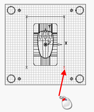
- Create the end point by clicking the last point again. To delete a line, use the
Delete key.
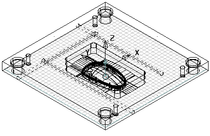
These layout pieces represent the layout of the cooling holes. As you enter the lines, the holes are displayed in the view on the wizard. You only need to enter the layout of the cooling circuit and not the positions of the holes. The positions of the holes are automatically calculated by the wizard.