Draft surfaces can be generated from a set of surfaces or from a composite curve. The creation method is similar for both starting objects.
When draft surfaces are generated from a set of surfaces, PowerShape generates composite curves, known as draft curves, on the surfaces. Each draft curve generates a draft surface as follows. One side of the draft surface is the draft curve. The draft surface projects along the draft angle until it touches either:
- the principal plane.
- a group of surfaces.
If you are not satisfied with the automatically generated draft curves, you can generate draft curves from a surface using the Wireframe tab > From Selection > Draft Curveoption, and then edit them.
When a draft surface is generated from a composite curve, PowerShape treats the composite curve as a draft curve. In this case, you can vary the draft angles along the draft surface.
- Click Surface tab > Manufacture panel > Draft.
- Use the Draft Surface dialog to create the draft surface:
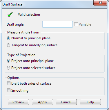
Use the options on the dialog as described below:
Valid selection — If valid objects are selected, a check is displayed. Select one of the following:
- A composite curve.
- One or more surfaces.
- One or more solids.
Draft angle — The angle at which the draft surface is projected from the selected objects. You can use a negative angle when creating a draft surface.
Variable — This option is only available if you are creating a draft surface from a composite curve. It enables you to create a draft surface with variable draft angles.
When this option is selected, the Preview button is unavailable. When you click Apply, the Variable Draft dialog is displayed. Use this dialog to input the variable draft angles.
Measure angle from — The draft angle is measured (by default) from the axis normal to the principal plane. The Tangent to underlying surface option is only available if you are creating a draft surface from a composite curve that lies on one or more surfaces.
If you are creating a draft surface from surfaces or solids, an arrow is projecting out from the surfaces. It is parallel to the axis normal to the principal plane and is used to calculate where the draft curves lie on the surfaces.
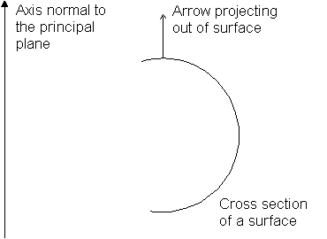
Remember that one side of the draft surface is defined by the draft curve.
The points of the draft curves are positions on the surfaces where the angle between the tangent and the arrow equals the draft angle.
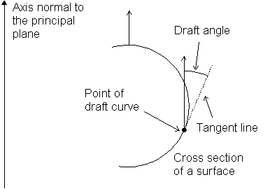
The draft surface is projected along this tangent until it touches whatever you select as the Type of Projection on the dialog.
Click the arrow to change its direction if you want the draft surfaces to project in the other direction.
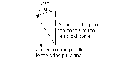
If you are creating a draft surface from a composite curve, two arrows are drawn on the composite curve. Both arrows determine the direction of projection of the draft surface.
With Normal to principal plane selected from Measure angle from options, one arrow is parallel with the principal plane and the other with the axis normal to the principal plane (see below).
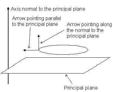
The draft angle is measured between the arrows as shown below.
You can change the direction of the arrows by clicking them or typing one of the following commands in the Command window:
- REVERSE PROFILE — reverses the 'normal' direction instrumentation arrow.
- REVERSE WITHDRAWAL_DIRECTION — this reverses the withdrawal direction instrumentation arrow.
Ensure that the arrow along the normal to the principal plane points in the correct direction, usually in the direction of the split surface.
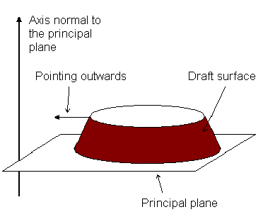
If you require a draft surface that projects outwards, ensure the arrow parallel to the principal plane points outwards:
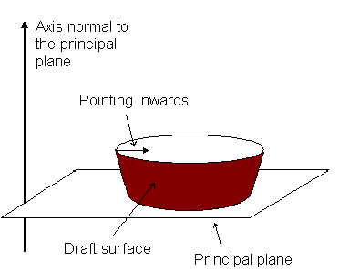
If you want a draft surface that projects inwards, ensure the arrow parallel to the principal plane points inwards:
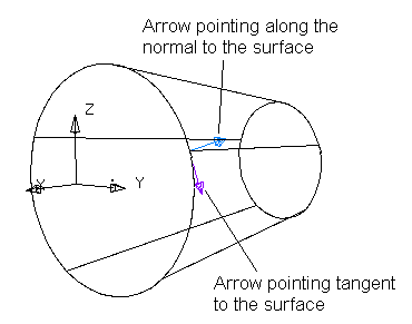
If your composite curve is created from the underlying surface, you can use the tangent data of the surface to define the draft angle. To use the tangent data, select Tangent to underlying surface from the Measure angle from options. The arrows change direction such that:
- the arrow pointing parallel to the principal plane now points along the normal of the underlying surface;
- the arrow pointing normal to the principal plane now points tangent to the surface.
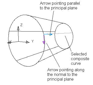
Consider the following composite curve on a surface. With Normal to the principal plane selected (by default) from the Measure angle from options, the arrows point as shown below.
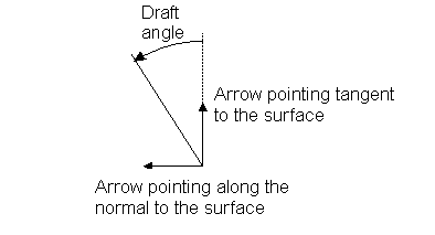
With Tangent to underlying surface selected, the arrows point as shown below.
The draft angle is measured between the arrows as shown below.
You can click the arrows to change their direction.
In our example, the following draft surface is created when we enter a draft angle of 5 .
.
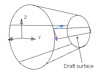
Type of projection — This allows you to choose where to project the draft surface:
- Project onto principal plane — This option projects the draft surface onto the principal plane.
-
Project onto selected surface — You can project the draft surface onto a number of surfaces. Select the surfaces and a TICK appears in the box. If the surfaces overlap one another, the draft surface is projected onto the surface nearest to it.
Note: If the draft surface does not entirely project onto the surface or the plane, a draft surface is created on the portion of the surface or plane that it can project onto.
Options:
-
Draft both sides of surface — (Available only when creating draft surfaces from surfaces.) This ignores the arrow projecting out of the surfaces and creates draft surfaces from both sides of the surfaces.
Note: If the surfaces are not symmetrical about the surfaces or principal plane onto which the draft surfaces are projected, PowerShape matches the draft surfaces by increasing the draft angles along the draft surfaces, where necessary.
- Smoothing — This smooths out any ripples in the surface. It frees projected tangents where appropriate and preserves straight spans.
Preview — Displays the draft surface using the current settings on the dialog. You can continue to change the settings on the dialog until you are satisfied with the previewed draft surface.
Apply — Creates draft surfaces in the model, trims the set of selected surfaces to the draft curves. The dialog remains on the screen for you to select more objects and continue creating draft surfaces.
Cancel —Closes the dialog.
You may wish to edit the outer boundary of the draft surface. A draft surface is a power surface and is edited accordingly. For further details, see Editing Power Surfaces.