This option lets you check if a mold design has any undercut areas. Undercut areas show where it would be difficult to separate the part from the mold.
By using Undercut shading, you can help reduce costs because you can check the model for any areas of undercut before manufacturing the model. If any areas of undercut are found, the surfaces can be adjusted to remove them.
Undercut shading visualizes the draft angle at all points on the surface. The draft angle is measured between the surface normal and the split plane. The split plane is the XY plane of the current workspace.
Suppose we have the following mold design:
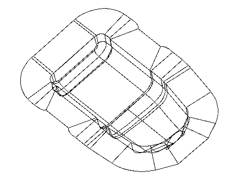
We can use Undercut shading to show areas where it will be difficult or impossible to extract our mold tool:
- Set the required minimum draft angle using the
Draft Angle text box on the
Surface Analysis
page of the
Options
dialog.
The Options dialog is displayed by choosing File > Options > Application Options.
- Click Visualisation tab > Shading panel > Undercut.
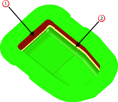
The model is now shaded in three colours to show areas of undercut:
Red — This warns you that the area will be undercut, because the draft angle on the model is less than the required minimum angle.
Yellow — This warns you of possible undercutting, because the draft angle is greater than, but within a given warning angle of, the required minimum angle.
Green — This area is well clear of undercutting.
Our mold is shaded as follows:
Adjust the surfaces in the red
 (and possibly yellow
 ) to avoid undercutting.