With the source component displayed:
- Click Wizard tab > Modify Molds panel > Component.
- In the
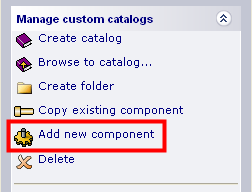
Choose a Component dialog, click
Add new component.
- Select the following:
- Source component on the model.
- Destination folder.
- Click Use selected.
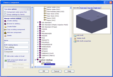
- Click
Add to add the component to the custom catalog. The dialog updates to display the component:
- Click Edit component details and dimensions to display the MS Excel spreadsheet for the component.
- Change the name and dimensions in the spreadsheet as required. Switch back to PowerShape.
- Click
Apply changes to:
- Update the Custom Catalogs tree to reflect any component name change.
- Close the spreadsheet.
- Display the component in the graphic window on the dialog.
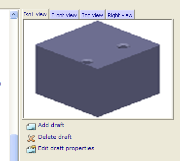
- Use the following options as required:
- Click
 to
Add draft. Choose the required graphic from the
Select a Draft dialog. The selected graphic is added to a
Draft tab.
to
Add draft. Choose the required graphic from the
Select a Draft dialog. The selected graphic is added to a
Draft tab.
- To delete a tab, select the tab and click
 to
Delete draft.
to
Delete draft.
- To change the title of a tab, select the tab and click
Edit draft properties. Enter the new tab
Title and click
OK (just below the
Title) to change the tab.
- Click
- Add further user-defined components as required.
- When you have added all components to the custom catalog, click OK to finish.
Preview of a user-modelled component
Any user-modelled custom component that is added to a custom catalog displays a preview when it is selected from the catalog.

The preview reflects the component geometry that is stored in the solid tree.
The following example shows the preview that is generated if you have created a custom component where the hole depth is greater than the dimension of the block.
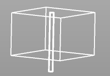
If required, you can modify the geometry of the component and create a new component from the modified geometry.