- Click Wizard tab > Mode panel > Toolmaker On/Off to run Toolmaker.
- Click Wizard tab > Modify Molds panel > Power Feature Trimming.
The Power Feature Trimming page is displayed.
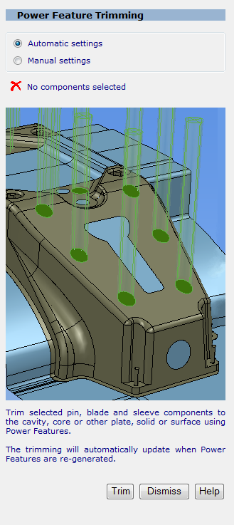
- Select
Manual settings if you want to specify the parameters to be used for trimming the pins. The
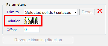
Parameters area is displayed
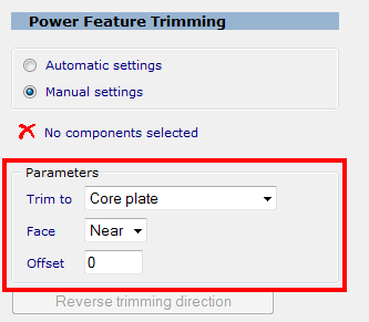
- In the
Trim to list, choose an option to specify the plate:
Core plate (available when core pin, ejector sleeve or ejector pin components are selected)
Cavity plate (available when core pin or return pin components are selected)
Selected component
Selected solid / surfaces
- In the
Face list, choose the face of the plate to trim:
Near
Far
If you select components with different functions (for example, an ejector pin and a return pin), the Trim to drop-down list contains all options (Core plate, Cavity plate, Selected plate, Selected solid /surfaces). When you click Trim, a dialog asks you to confirm you want to apply trimming to all selected pins. - Click
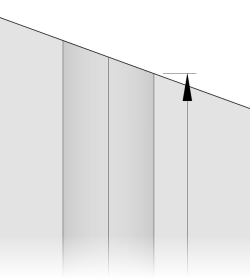
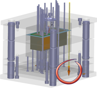
Reverse trimming direction if you want to change the trimming direction for selected components in the model. The trimming direction for individual selected components is indicated by an arrow.
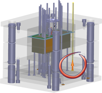
You can change the trim direction for a component by clicking the arrow.
- In the
Trim to list, choose an option to specify the plate:
- Click
Trim to apply the changes when you generate the Power Feature.
Note: To undo trimming operations, click
 on the Quick Access toolbar.
Tip:
on the Quick Access toolbar.
Tip:- When trimming to a surface, the Solution buttons ensure the correct part of the pin is left in the model.
Tip: When using ejector pin trimming, the depth of the fit hole is measured from the lowest point of the trimmed region of the ejector pin. This allows holes to have sufficient depth when they are trimmed to a steep 3D face.