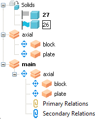
The assembly tree, shown in the Explorer window, displays all the assemblies and solids in the model.
Each assembly contains all its components and the relationships between the components. In this example, there are two assemblies; axial and main, and two solids; 26 and 27, that are not part of either assembly:

 — Click this button to expand the branches in the tree.
 — Click this button to contract the branches in the tree.
Solid trees and assembly trees are displayed together to provide an integrated product. This enables assembly modelling and solid modelling functionality to be used in parallel. Solids that are not part of the assembly are displayed at the top of the tree, either as a single solid, or, if there a several solids, in the Solids branch:

