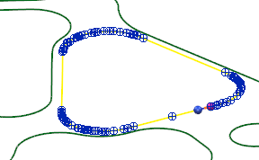
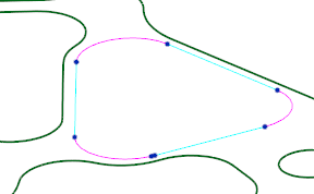
The Arcs to Planar Curves fitting option simplifies and re-fits composite curves with arcs and lines.
|
Before Arc Fitting
|
After Arc Fitting
|
Use this option to simplify composite curves that have been created from meshes, solids, or surfaces. Creating surfaces and solids from wireframe becomes much easier by converting a composite curve with many points, into a collection of arcs and lines with few points.
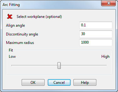
You can control the settings using the Arc Fitting dialog.
To access the Arc Fitting dialog:
- Select a curve and click Curve Tools tab > Fit panel > Arcs to Planar Curves.
- Click the Arc fitting options
 button on the
Dynamic Sectioning dialog or the
Oblique dialog.
Note: A preview of the original curve is shown when using Arcs to Planar Curves from the Manage tab > Fit panel.
Use the options on the Arc Fitting dialog to change the Arcs to Planar Curves settings:

- Select workplane — If a workplane is not selected then the best-fit workplane is used. You can select a workplane to use, and the curve will be projected onto its XY plane.
- Align angle — This option controls alignment of lines within the workplane. Lines that lie close the principal axes with an angle less than the entered value, are snapped to the principal axes. Set to 0 to disable principle axis alignment. Takes values between 0 and 10.
- Discontinuity angle — Enter a value to set the maximum angle allowed between lines on the composite curve. If the angle between two lines is greater than this angle, additional spans are added to reduce the angle. Takes values between 0 and 90 degrees.
- Maximum radius — Enter a value to set the radius limit at which arcs will be drawn. Curves with a radius greater than this value become arcs, and curves with a radius lower than this value become lines.
- Fit — Use the slider to control the fit tolerance. A Low fit sacrifices quality by increasing simplicity and reduces the number of curves. A High fit sacrifices simplicity by creating more curves, however retains a high accuracy to the original curve.

