This shading lets you specify a radius for a tool. The model is then compared with the tool size and areas where the model would be machined to size or where material would be left are highlighted.
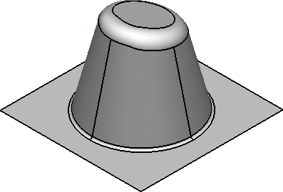
Suppose we have the following model on the screen:

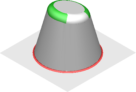
We will shade it using Minimum Radius shading to show any areas where material would be left on:
- Specify the Cutter Tip Radius of the tool you want to use to check the model using the Surface Analysis page of the Options dialog (displayed by clicking File > Options > Application Options > Tools > Analysis > Surface Analysis).
- Click Visualisation tab > Shading panel > Minimum Radius.

The model is now shaded to show areas that can be machined to size and any areas where material would be left on. Each colour of the shading is discussed below:
- Red — This shows areas where the concave radius is less than the cutter radius. Machining here leaves material on. However, if you decide to machine the model from the underside then these areas will be machined to size.
- Green — This shows areas where the convex radius is less than the tool radius. These areas will be machined to size. However, if you decide to machine the model from the underside (for example, machine a cavity as opposed to a punch) these areas will leave material on.
- White — These areas will machine to size.