Use this tab to create patterns of objects on wireframe items.
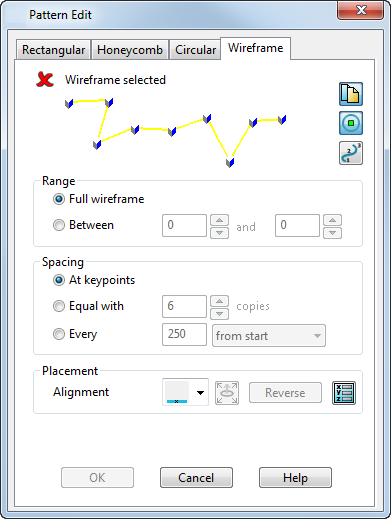
To create patterns of objects on wireframe items, you need to:
- Select the pattern objects.
- Display the Wireframe page of the dialog.
- Select the wireframe item that you want to create the pattern on.
- Use the options to determine how the elements are created on the wireframe.
 Create a copy of the pattern wireframe — You can choose to create a copy of the wireframe or delete it. Click this button to toggle between the two options.
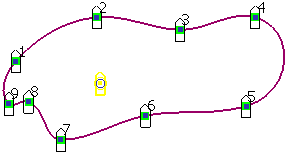
 Display suppress markers — This displays a marker on each pattern element. Click on the markers to turn off individual elements in the created pattern.
 Toggle curve point display — This turns the display of point numbers on the wireframe on or off.
Range
Set the range of the wireframe to create the pattern effect that you want:
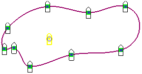
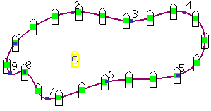
- Full wireframe — Select this option to include the whole wireframe item when creating the pattern elements, as shown in the example above.
-
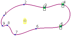
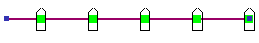
Between — Select this option and specify the range of point numbers on the wireframe you want the pattern to be created between. In the example below the pattern is created between points 3 and 5.
Click
 to display the
Position dialog to specify the position of the present point.
to display the
Position dialog to specify the position of the present point.
Spacing
Specify how the wireframe is used to position elements:
- At keypoints — Select this option to create the pattern at the key points on the wireframe, subject to the range you have specified.
-
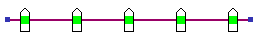
Equal with — Select this option and specify the fixed number of copies of pattern elements to be created within the range specified. The example below shows the pattern created with 20 copies.
-
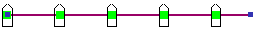
Every — Select this option and specify the spacing distance for the elements in the pattern. Choose an alignment option from the drop-down list:
-
from end
-
from middle
-
from start
You can also open the Position dialog to specify the position of the present point.
-
from end
Placement
Choose an alignment suitable for the pattern effect you want:
-
 Copy along wireframe — This creates a copy of the pattern element at the points and range specified. This is the default setting.
-
 Rotate copies to axis — This displays two points on the original pattern element, initially in the same position, approximately at the centre of the original pattern object. You position these points to create an axis that can be used to align with the normal of the curve.
If the curve does not have surface dependencies, the pattern aligns to the normal of the curve. If the curve has surface dependencies, the pattern aligns to the normal of the surface.
The Set plane of pattern option becomes available.
- Select the pattern element.
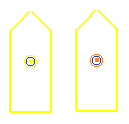
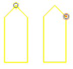
- Use
 to toggle between the selection of the points. The points are different colours.
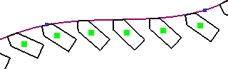
- Click on each point and move them into the positions where you want to create an axis to align with the normal of the curve.
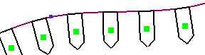
The example below shows the pattern element aligned with the normal on the curve at the axis between the two points. - Click the Reverse button to change the normal and create the pattern on the other side of the curve at the same axis.
 When reversed, the pattern changes as shown below:
- Click
to display the
Position dialog to specify the position of the present point.
-
 Place two points on wireframe - This displays 2 points on the pattern element. Use
to toggle between the selection of the points and position them to choose the part of the pattern element you want to lie on the wireframe.
Place two points on wireframe - This displays 2 points on the pattern element. Use
to toggle between the selection of the points and position them to choose the part of the pattern element you want to lie on the wireframe.
The example below shows the points positioned on the edge of the pattern element, and the pattern elements created on the wireframe.

-
Set the point to be repositioned - This is used with the Alignment options to move the point markers on the pattern element.
- Reverse - This flips the side of the wireframe where the pattern will be created, corresponding with the curve normal. For example, inside or outside.
-
Set plane of pattern - This option becomes available when the Rotate copies to axis option is selected from the Alignment drop down list. Use the Pattern Plane dialog to set the coordinates for the alignment of the pattern elements on the wireframe. The workplane can also be edited dynamically. The normal of the pattern is along the Y axis and the tangent of the pattern is along the X axis.
The following additional options are displayed on the dialog if the object you have selected to produce the pattern is a feature. They are not displayed if the selected object just contains solid features.
-
Remove feature - Controls how the original feature is handled when the pattern is created. If selected when the pattern is created, the original feature is absorbed by the pattern and they become one feature. In the solid tree, the feature icon is replaced by a pattern icon.
If deselected when the pattern is created, the pattern is created as a separate feature and both the original feature and the pattern feature can be edited separately. The solid tree shows both the feature icon and a pattern icon.
This option is not displayed on the dialog if you are editing an existing pattern feature.
- Edit Definition - This option is only available when you are editing an existing pattern feature. When you select this option, you can edit the pattern feature using the appropriate dialog.
-
Remove feature - Controls how the original feature is handled when the pattern is created. If selected when the pattern is created, the original feature is absorbed by the pattern and they become one feature. In the solid tree, the feature icon is replaced by a pattern icon.
OK — Creates the pattern and closes the dialog.