This page lets you to specify the layout and clearances of the mold locks.
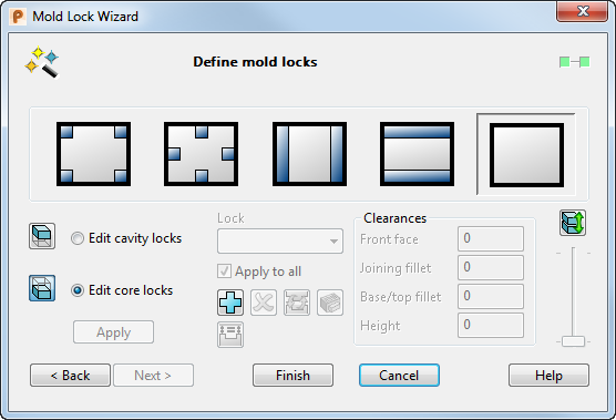
You can select a predefined layout for the mold locks or define your own layout by selecting the custom layout option and editing the locks accordingly.
|
|
Position four mold locks on the corners of the inserts |
|
|
Position four mold locks so that they are at the midpoint of the edges of the insert. |
|
|
Create a pair of mold locks running along the left and right edges of the inserts. |
|
|
Create a pair of mold locks running along the top and bottom edges of the inserts. |
|
|
Custom layout, with no preview locks initially. |


When using predefined layouts, the male lock half (the protrusion), is always added to the core insert and the female lock half (the pocket) on the cavity insert.
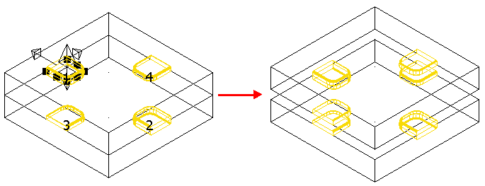
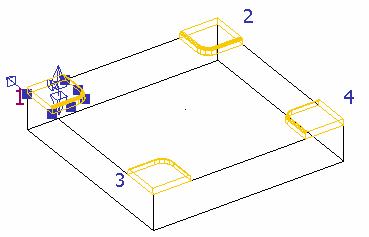
All the preview mold lock halves are displayed as instrumentation and the current active one has drag handles attached to it. The locks are labelled, using the same name that is displayed in the Lock drop-down list. The colour of the label for the active lock is a different colour to the labels for the other locks.
 — Show/hide the cavity insert.
 — Show/hide the core insert.
Edit cavity locks — Edit the cavity locks, with the corresponding changes being made to the associated core locks.
Edit core locks — Edit the core locks, with the corresponding changes being made to the associated cavity locks.
When you select Edit cavity locks or Edit core locks, the insert that you are not using is hidden to help editing. On start-up, Edit core locks is automatically selected and the cavity insert is hidden.
Lock — The name of the current active lock is displayed in the box. To change the active lock, select a lock from the drop-down list.
If Mold Lock Wizard has already used the inserts to create some mold locks, these are automatically identified and added to the Lock drop-down list. Any mold lock in the drop-down list can be edited using the options available on this page of the wizard.
Apply to all — Select this option to apply the changes that are made to the current lock, to all the other locks on the same layout. The option is unavailable if you are using a Custom layout; in this case you must edit each lock individually. Deselect this option to make changes to the current lock only.
 — Add a new lock to the inserts. This option is only available if you are using Custom layout.
To add a new preview lock,
Position the male half of the preview lock on the insert and click the left mouse button.
You can position the male half of the lock on either the cavity or core insert; the corresponding female half of the lock is automatically positioned on the other insert.
- Select the
Add a new lock
button. The preview lock is attached to the cursor. If necessary, you can detach the lock from the cursor by clicking anywhere on the graphics window, away from the two inserts.
- Position the male half of the preview lock on the insert and click the left mouse button.
- You can position the male half of the lock on either the cavity or core insert; the corresponding female half of the lock is automatically positioned on the other insert.
 — Delete a lock. This deletes both halves of the active lock. Another lock (if available) automatically becomes the active lock.
 — Toggle male/female lock halves. When you select this button, existing male lock halves are converted to female lock halves.
So, if the male lock was attached to the core insert and the female lock half was attached to the cavity, selecting this option would attach the male lock to the cavity insert and the female lock to the core insert.
 — Display the
Protrusion dialog for the currently active lock half. This lets you adjust the dimensions and positioning of the lock. Select
Accept on the
Protrusion dialog to apply the changes to the other half of the lock. If
Apply to all is selected, the changes are also applied to the other locks.
— Display the
Protrusion dialog for the currently active lock half. This lets you adjust the dimensions and positioning of the lock. Select
Accept on the
Protrusion dialog to apply the changes to the other half of the lock. If
Apply to all is selected, the changes are also applied to the other locks.
 — Select this option to position the tops of the male lock halves on the active insert, at the same Z position. This is set to the Z value of the lock with the highest Z position.
Clearances — These options specify the clearance between the male and female lock halves. There are four clearances that can be set at this point. If Apply to all is selected, any changes made in this section are applied to all locks in the current layout.
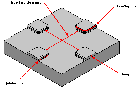
Front face — Enter a value to change the clearance between the front surfaces for the lock halves.
This option is only available if you are using the second layout option.
Joining fillet — Enter a value to change the joining fillet radius clearance between the halves. The joining fillet clearance is the one between the fillets that join the feature to the insert.
Base/top fillet — Enter a value to change the radius clearance between the female base fillet and the male top fillet.
Height — Enter a value to change the height clearance between the lock halves.
Any clearances that you set are applied to the inactive lock. So, if the height of the active lock half is 10 and you set the height clearance to be 1, the inactive lock half will be either 11 (if the inactive half is a pocket), or 9 (if the inactive half is a protrusion).
|
|
If you select the
Start/End opening simulation
|
 button, the slider is active, but all other options on the page are disabled. The slider can then be used to separate the inserts. The slider is disabled unless you are in simulation mode.
Apply — Creates locks from any preview locks that currently exist. If a mold lock half has an invalid definition, for example if a fillet radius is too large, the definition is marked by a series of dotted lines and a warning message is displayed.
The warning message tells you the lock half to adjust. You can either make an adjustment, or ignore the warning and create the locks.
Finish — Exit the Mold Lock wizard. If some preview locks exist, but you have not used Apply to create the locks, selecting Finish causes these to be created.