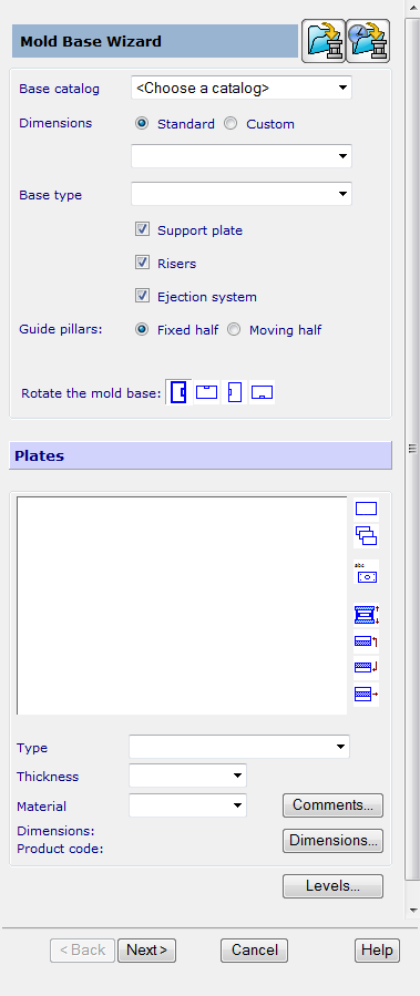
The first page of the Mold Base Wizard enables you to select the mold base and its components.
To specify the mold base:
- Choose an entry in the Base catalog list. If you have selected a catalog in the Cavity/Core Wizard, it is automatically selected and cannot be changed.
- Use the
Dimensions options to select the size of the mold base.
Alternatively, to create a custom mold base:
- Select the Custom option. Two boxes are displayed below the option.
- Enter your values and click Apply.
- Enter the dimensions in the boxes.
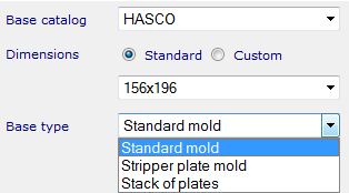
- Select the type of mold base from the
Base Type options.
When you choose Stack of plates from the Base type list, the wizard creates a mold that consists of one special plate, the Master plate.
You can then do one of the following:
- add optional plates to the mold using the plate list buttons
- enter the number of plates in the Number of Plates box and select Apply.
Note: Stack of plates is not currently supported by the Cavity/Core Wizard.Note: You cannot remove the master plate from the mold. - Deselect Support plate if you do not want to include a support plate in the mold.
- Deselect Ejector system if you do not want to include ejector plates as part of the mold.
- Select which half contains the
Guide pillars. Choose one of the following:
- Fixed half
- Moving half.
- Select one of the
Rotate the mold base options to rotate the mold to be created by 0
 , 90, 180, or 270.
The default rotation is 0
, so that the width of the mold base is along the X axis and the length is along the Y axis.
The Plates section displays a list of plates in the selected mold base.
- Select a plate from the list. It is highlighted on the model and its
Type,
Thickness, and
Material is displayed. You can set the
Type,
Thickness, and
Material available for each plate from the drop-down lists.
The following buttons work on the plate that is currently selected in the Plates list.
 — Make the selected plate plain.
 —- Make all the plates in the mold plain.
 — Rename the plate.

 — Attach an optional plate to the selected plate.
If the
option is selected, the inserted plate is attached unconditionally to the requested face of the selected plate. Positions of all other plates are unchanged. This option may be used to add optional ejector plates to the mold.
If the default
option is used, an optional plate is inserted on the requested face of the selected plate. All the other plates are moved to accommodate the optional plate.
On finishing the wizard, assembly modelling relations are used to attach the optional plate to either the selected plate or the plate above/below the selected plate. The position of the master cavity plate of the mold relative to the optional plate determines the final location of the optional plate.
 — Insert an optional plate above the selected plate.
 — Insert an optional plate below the selected plate.
 — Remove the selected optional plate. You cannot use this option to remove a predefined plate.
Note: You cannot insert an optional plate between the cavity and core plates if they have been created in the Cavity Core wizard. A mold with an optional plate between the cavity and core plates will not be detected by the Cavity Core wizard. The Dimensions information that is displayed indicates the units and if the selected plate is standard or custom.
— Remove the selected optional plate. You cannot use this option to remove a predefined plate.
Note: You cannot insert an optional plate between the cavity and core plates if they have been created in the Cavity Core wizard. A mold with an optional plate between the cavity and core plates will not be detected by the Cavity Core wizard. The Dimensions information that is displayed indicates the units and if the selected plate is standard or custom. - Click
Dimensions to change the dimensions of the selected plate. This displays a dialog for Define a component.
If you used the Cavity-Core Wizard, the correct Type, Thickness and Material for the cavity and core plates are automatically entered. You can alter these values for inserted and empty pocket modes.
- Click
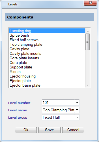
Levels to specify the level for each component of the mold base. The
Levels
dialog is displayed.
By default, components are created on different levels. The levels for the components are put in two groups: moving half and fixed half.
- In the
Levels dialog:
- Select a component from the list.
- In the three
Level boxes, you can see the details of the level it will be created in.
Level number — Edit the level number by either typing in a value or selecting a number from the list.
Level name and Level group — Use these to change the details about the level.
- Click one of the following:
OK — Creates the components on the specified levels.
Save — Stores the details of the level for each component. These details are then available for new molds.
- Click Next to display the second page of the Mold Base Wizard.