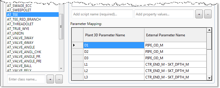
Once you have added a class to the Class Mapping tab, you must also add it to the class list in the geometry tab for conversion to be successful.
You can specify a 3D shape to use and map the parametric dimensions to size it accurately. In other words, you are describing what each class should look like in the model.
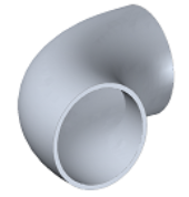
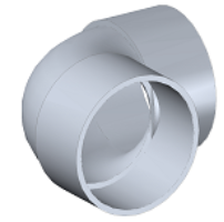
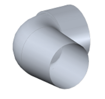
Plant 3D shapes have defined connection ports. They also have names that help identify the end type, and these names are appended to the script name. Shape names without an underscore extension are buttwelded/beveled, and can often accommodate flanges as well. Shape names ending with _OF indicate that the port has threaded female or socketweld female ends. Shape names ending with _OM indicate that the port has threaded male or socketweld male ends.
Following are examples of commonly-used graphic scripts:
| Sample Script name | Sample Descriptions | Sample Image |
|---|---|---|
| CPB (names without an underscore extension) | Beveled, buttwelded, or flanged endtypes |
 |
| CPB_OFOF | Female socketweld or threaded endtype on each port (_OFOFOFOF indicates a 4-way valve with a female socketweld or threaded endtypes on each port) |
 |
| CPB_OMOF | Female socketweld or threaded endtype on one port and male socketweld or threaded endtype on the other port |
 |
| CPB_OMOM | Male socketweld or threaded endtype on each port |
Identical to CPB_OMOF in the previous example, but with male endtypes on each port |
| CPJRCL | Concentric reducing component |
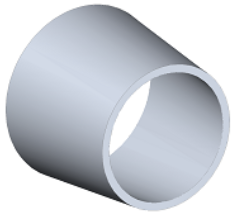 |
| CPJREL | Eccentric (offset or center line shift) reducing component |
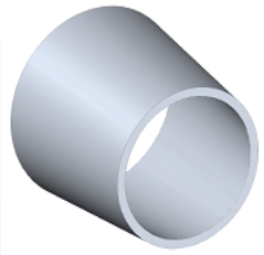 |
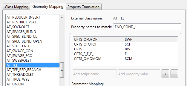
Each script has associated properties that indicate how the endtypes are to be drawn. AutoPLANT or CADWorx properties are matched to AutoCAD Plant 3D toolset versions. In many cases, you may want a class to have different shapes, depending on context. For example, you may want AT_TEE (AutoPLANT) or Tee (CADWorx) to have a welded tee, a socked-welded tee, or a flanged tee in different locations. You can specify a property name or names to match as criteria for the graphical shape to be used.
For AT_TEE, for example, you can specify the external property END_COND_1 as the matching criteria to help differentiate when to use the different shapes. Following is an example that specifies using CPTS_OFOFOF when END_CONDITION_1 is SWF or SCF, but using CPTS when END_CONDITION_1 is BW, and so on.
For each geometry mapping there is also a corresponding set of parameters, and these can vary depending on the shape. The image that follows shows a Plant 3D threaded female tee in the catalog editor (size tab) along with its parameters.
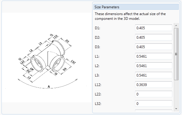
You can enter these parameters in the mapping table in the Plant 3D Parameter Name column and map them to the corresponding AutoPLANT property name (or value).
