You can use the Branch Table Editor to assign branch fittings when routing pipe in an AutoCAD Plant 3D toolset model.
When you route pipe in an AutoCAD Plant 3D toolset model, branch table assignments determine the type of fitting the piping model uses when joining branch and header pipes.
You use branch table information in a spec to cross-reference the size of a header with the size of a branch and insert the appropriate fitting into an AutoCAD Plant 3D toolset model.
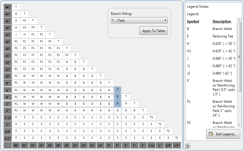
In the branch table, the cell where the header size column and branch size row meet displays a legend symbol that identifies the fitting to use for that branch. You can assign more than one legend symbol to a branch cell. For example, you can assign both a reducing tee and a latrolet to the same 3” x 4” cell.

A tee, reducing tee, latrolet, and sockolet, are some of the branch types you can set in the branch table.
Assign Branch Fittings to Use in a Piping Model
You perform the following steps to assign fittings in the branch table:
- Identify all branch fittings in a spec to use in a piping model. In the spec, you select which fittings to use in the branch table. The fittings you select appear as symbols in branch table cells, and are referenced in the legend of the branch table.
- When more than one fitting of a specific size is available as a branch, set the default branch fittings.
- Assign branch fittings to cells in the branch table for all header and branch pipe size matches.
You can add more than one fitting to a branch table cell. In addition to default parts, you can add additional parts to be available when routing and branching pipe.
Customize the Branch Table
You can change the position and label of the Header and Branch axes in the branch table. By default, the Header axis is positioned at the bottom of the table and the Branch axis is positioned at the left. You can also add notes to the legend, add shading to branch table cells, and choose to display or hide the branch table legend.