- Create a block (for example: an insulation block).
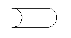
- Add an attribute to the block and call it UNASSIGNED.
- (Optional) Add dynamic sizing behavior to the block attribute by adding a linear parameter to determine sizing behavior as follows:
- To have the linear parameter automatically size to match the attribute text size, name the distance label of the linear parameter the same as the attribute definition tag. An example of this dynamic sizing behavior is the stretching of underlining in the Equipment Tag style.
- To have the linear parameter automatically size to include the entire X or Y extents of all the evaluated attributes in the block definition, give the linear parameter the names TotalXand/or TotalY. An example of this dynamic sizing behavior is a block definition consisting of a rectangle enclosing several lines of attributes. The rectangle stretches or shrinks to accommodate the attributes regardless of their values.
- Save the block drawing.
- On the ribbon, click Home tab
 Project panel Project Manager Project Setup.
 - In the Project Setup tree view, expand Plant 3D Class Definitions.
- Continue to expand the list until you locate and click a class definition.
- On the Class Settings pane, under Annotation, click Add Annotation.
- In the Symbol Settings dialog box, Symbol Properties, locate and click Symbol Name. Enter new name for the annotation style.
- Under Symbol Properties, locate and click Block. Click the [...] button.
- In the Select Block Drawing dialog box, browse to and select the drawing that contains the block you want to use. Click Open. Note:
You cannot use a drawing file as a block for the symbol. The block you use must be in the drawing file that you select.
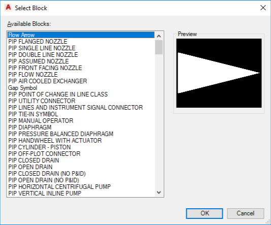
- In the Select Block dialog box, under Available Blocks, select a block. Click OK.
- In the Symbol Settings dialog box, under General Styles Properties and Other Properties, change the properties as needed. Click OK.
- In the Project Setup dialog box, under Annotation, click Edit Block.
- On the small Annotation ribbon, click Assign Annotation Format
 . In the Block Editor window, select the attribute definition.
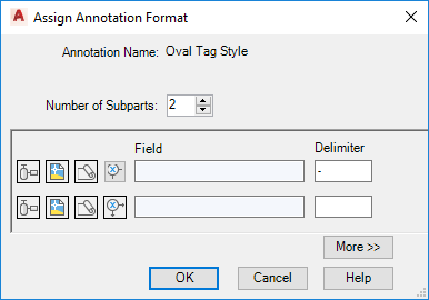
- In the Assign Annotation Format dialog box, create each subpart of the format string as follows:
-
 To select a class property, click Select Class Properties.
 -
 To select a drawing property, click Select Drawing Properties.
 -
 To select a project property, click Select Project Properties.
 -
 To define an expression, click Define Expression.
 - Enter a delimiter to use between the fields. You can enter text and special characters. For example, if you want a pump to have text reflecting the flow rate data, you could use a field value of #(TargetClass.FlowRate) and a delimiter value of GPH. To add leading text, create the format string and add the leading text using the Properties palette or the Attribute Definition dialog box. For example, to create an annotation for an Exchanger that reads TUBE [pressure] @ [temperature], use the Assign Annotation Format dialog box to create the format string #(TargetClass.TubeDesignPressure) @#(TargetClass.TubeDesignTemperature). Then add the leading text TUBEusing the Properties palette or the Attribute Definition dialog box. Note:
If you manually add leading text, update any associated dynamic block parameters to match, using the Properties palette.
- To create more subparts to the format string, in the Number of Subparts box, click the Up arrow or enter a number. Click OK
-
- In the Assign Annotation Format dialog box, click OK.
- In the Block Editor, click Close Block Editor. Save the block.
- Click OK to close the Project Setup dialog box and return to the drawing.
- In the drawing, right-click the appropriate component or line to make sure that the new annotation is on its shortcut menu.
The following procedure illustrates how to create an annotation without using an existing block as a template.