Tool palettes display standard and custom component and line symbols that you place to create your drawings.
The standard you choose when you create a project dictates which tool palette is displayed when you start the program. For example, if you create a project using the ISA standard, the initial tool palette displayed is the P&ID ISA palette.
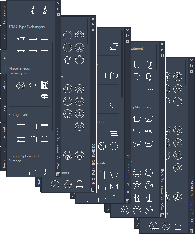
You can switch to another tool palette by right-clicking the tool palette title bar and selecting a tool palette. However, not all P&ID symbols that are available in one standard are the same in other standards.
For example, you have created a project using the PIP standard and have begun adding lines and components from the P&ID PIP tool palette. If you change to the P&ID ISA tool palette and attempt to add a 4-way valve, you receive a warning in the status bar stating that the ISA 4-way valve symbol cannot be found in the current palette. To add a 4-way valve, return to the P&ID PIP tool palette and select the 4-way valve from that set of symbols.
If you are working in a project using the ISA standard, you can add lines and components from the PIP standard. Also, if you are working in a project using the DIN standard, you can add lines and components from the ISO standard. In both cases, you might receive a warning for specific lines or components, but you can use most symbols without restriction.
You can also create your own custom tool palette by right-clicking the title bar of the tool palette and clicking New Palette. You can then add tools to the palette. For more information about creating a tool palette, see “Customize Tool Palettes” in the AutoCAD Help system.
If you do not see the P&ID workspace interface elements in your drawing area, it is likely that you are not displaying a P&ID workspace. Verify that you are using a P&ID workspace by clicking Workspaces on the status bar and clicking a P&ID workspace.