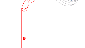
You can create iso information items (markers) such as floor symbols, flow arrows, break points, and then place them on your 3D model. The information item is displayed on the generated isometric drawing.

Markers placed in the model display as spheres inside piping.

Information items can add symbols and annotations to the Iso drawing. Information items can also change how the Iso is generated.
You can specify Iso splits by adding a Break Point marker to the model. You can also add a field weld in the model to specify an Iso split location.