Custom Equipment
You can convert AutoCAD or Inventor models to an AutoCAD Plant 3D toolset equipment model.Attaching AutoCAD Objects
You can add graphics to equipment, making them part of the equipment.
Attached graphics may include objects such as brackets, davits, clips, boots, domes, or integral railings.
Once you add a graphic to an equipment model, it becomes part of the model, and is moved, copied, or deleted along with it.
To edit an attached graphic, first detach it from the equipment. After editing, you can attach it again.
Equipment Modeling
You can now add equipment trim in the 3D model. New equipment trim includes:
- Stiffening Ring
- Skirt
- Platform
- Lug
- Body Flange


Common dimensions like vessel diameter use acquire mode that let you update a diameter once, and have the rest of the vessel update accordingly.
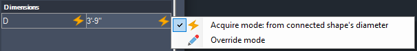
If the diameter of the main cylinder is set, the vessel head and trim diameter are also updated.
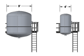
For example, changing the Diameter of just one shape from 9' to 4' updates all connected shapes and adjusts attached trim.

In addition to the new equipment trim features, semi ellipsoidal and flat head shapes have been added for a vessel head. Thickness has been added to some head shapes. You may need to first remove the existing head shape to set new parameters.
For more information see: About Equipment Shape Trim.
New Shapes
For less common pieces of equipment (such as turbine compressors), you can build your own equipment by selecting and assembling shapes along a vertical or horizontal axis.
You define the stacking order of the shapes along the axis, and specify the dimensions and placement parameters for the equipment. Depending on the shapes, you can also define the number, location, and dimensions of nozzles.
The shapes for pumps and strainers are fixed. You cannot add, delete, or change the shape of these equipment types. However, you can change their dimensions.
As the following illustration shows, you can create a vertical column by placing a large cylinder at the bottom, a cone stacked above it, a narrow cylinder on top of the cone, and a dish head on the top. You specify the height, dimensions, and other parameters as you add each shape.
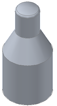
For vertical equipment, shapes are stacked along a vertical axis, from top to bottom. For horizontal equipment, shapes are stacked along a horizontal axis, from left to right.
The following table lists the shapes that are available for creating user-fabricated equipment.
| Shape | Preview Image | Description | Dimensions |
|---|---|---|---|
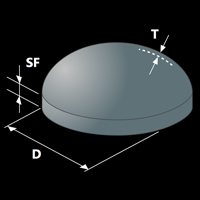
| 2:1 Torispherical Head |
|
A dished, spherical head with a flange. | Diameter (D)
Straight Flange Height (SF) Thickness (T) |
| Semi Ellipsoidal Head |
 |
A head that is in the shape of an ellipse, such that the long axis is twice the length of the short axis. The head depth is one-quarter the diameter. Does not have a flange. | Diameter (D)
Straight Flange Height (SF) Thickness (T) |
| Flat Head |
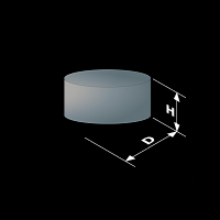 |
Diameter (D)
Height (H) |
|
| 2:1 Ellipsoidal Head |
 |
A head that is in the shape of an ellipse, such that the long axis is twice the length of the short axis. The head depth is one-quarter the diameter. Has a flange. | Diameter (D)
Straight Flange Height (SF) Thickness (T) |
| Round-to-Rectangle |
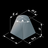 |
Orientation Depth (D1) Width (W) Height (H) Diameter (D2) Eccentricity (E) Rotation (A) |
|
| Pyramid |
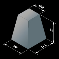 |
Orientation Bottom Depth (D1) Top Depth (D2) Width (W) Height (H) |
|
| Halfsphere |
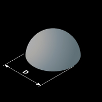 |
A head that is one-half of a sphere. The depth is equal to half the diameter. Used for high-pressure vessels due to its inherent strength. Expensive to manufacture because of the higher surface area, so it is only used when necessary. | Diameter (D) |
| Cylinder |
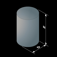 |
Diameter (D) Height (H) |
|
| Cone |
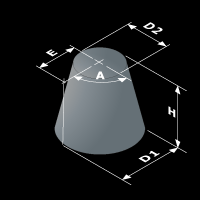 |
Orientation Bottom Diameter (D1) Top Diameter (D2) Height (H) Eccentricity (E) Rotation (A) |
|
| Cube |
 |
Depth (D) Width (W) Height (H) |