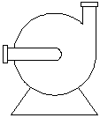
- Create a new block (for example: a horizontal centrifugal pump) and save the drawing file. If you do not know how to create a block, see “Create and Store Blocks” in the AutoCAD Help system.
- On the ribbon, click Blocks & References tab
 Block panel Block Editor.
 - In the Block Editor dialog box, click Current Drawing. Click OK.
- Turn off Midpoint snaps if they are on.
- On the Parameters tab of the Block Authoring palette, click Point Parameter, and place a parameter (for example: on the inlet of the pump).
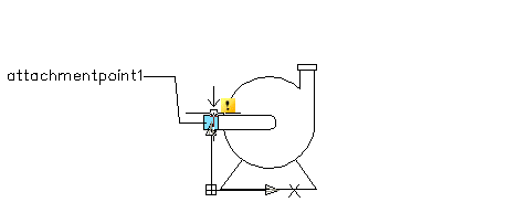
- Right-click the parameter. Click Properties.
- In the Properties palette, under Property Labels, click Position Label. Enter attachmentpoint1.
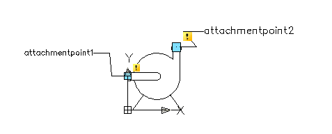
- Click a blank space in the drawing, and then press ESC.
- Create another parameter (for example: at the outlet of the pump), and label it attachmentpoint2.
- Save the changes and close the Block Editor.
- In the Project Setup tree view, expand P&ID Class Definitions.
- Continue to expand the list until you locate and click the component whose symbol you want to edit (for example: EquipmentPumpsCentrifugal Sump Pump).
- Right-click the class definition. Click New.
 Note:
Note:Instead of creating a new class definition, you can also add a new symbol to an existing class definition.
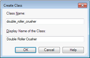
- In the Create Class dialog box, enter a name for the new class definition (for example: horizontalcentrifugalpump) and a display name (horizontal centrifugal pump).
- Click OK.
- Expand the node where the new class definition was added, and select the new class definition.
- On the Class Settings pane, under Symbol, click Add Symbols and follow the steps for adding symbols to component class definitions.
The following procedure illustrates how to create a pump (an endline component) and define two attachment points (where schematic lines will snap). You can create other components using the same general steps. Not all components require attachment points (for example, tanks do not require them) unless you want to define them.
Note:
Before you start this procedure, make sure the P&ID tool palette is displayed in your drawing and that the active tool palette tab is the one where you want to add the new component. For example, if you are adding a pump to the tool palette, make sure that the Equipment tab is active.