You can create piping by specifying the start point, continuing from an open port, or converting centerline objects into piping.
By default, the points you specify are on the center line of the pipe, but you can choose from a number of alignments (for example: bottom of pipe). For more information about aligning pipes, see Offset Pipe Placement.
Fittings (for example: elbows) are added when you change direction while continuing to route pipe from the previous end point.

In addition to specifying the end point in the model, you can type a distance to specify the position of the next fitting. For more information about the tools and procedures that help you place pipe at exact locations see Precision Location.
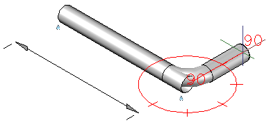
When you change direction, you can pick a point that aligns with the next pipe segment. Pipe length is cut back for the fitting.
As you add pipe segments, the pipe spec provides a list of fittings available to make the connection. If more than one fitting is available, a default fitting is selected based on the part use priority. For more information about fitting priority, see Modify Specs.
You can attach pipe to equipment nozzles using node object snap. Connection hardware (for example: a weldneck flange, gaskets, and bolts) is added from the pipe spec, based on the size and type of the nozzle.
You add a pipe using the ribbon, a Continuation grip, the spec viewer, the tool palette, or the plantpipeadd command.
Create Pipe From a Centerline
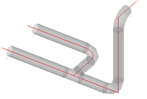
It can be easier to draw a piping centerline than to route piping directly. You can convert a centerline, which is drawn using AutoCAD objects, into pipe and fittings.
Sloped Piping
When you specify points for a pipe route at the same elevation, AutoCAD Plant 3D toolset can roll or cutback elbows to apply a desired slope.
![]() A slope glyph displays in the compass to indicate piping is sloped while routing.
A slope glyph displays in the compass to indicate piping is sloped while routing.
You can apply slope to pipe that is in the model using the plantpipeslope command.