Without specifying a start point, the beginning of the line can be arbitrary. You can place a start point in the 3D model to specify a start point.
-
 On the ribbon, click Isos tab
 Iso Annotations panelStart Point.
- Specify a point near the start of the line. The start point displays in the 3D model.

- In the drawing area, specify an insertion point on the center line of pipe or a fitting. For example, node snap to a valve port.
 If the marker is obstructed, switch to wireframe view.
-
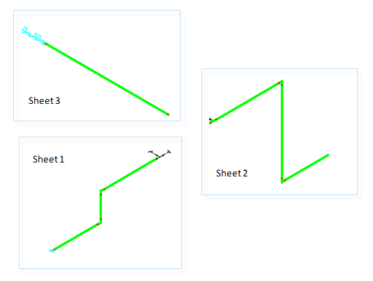
If you create new isometric drawings, the valve assembly now displays on sheet one.

Note: You can save the isometric start point in the 3D model at the same time you save split points. Placing a start point manually is required only if the default start point is not correct.