Use this dialog to define the parameters of an RC beam.
Access
- Click Design
 Required Reinforcement of Beams/Columns - Options Code parameters to open the R/C Member Type dialog, and then click
  .
. - Click
 (R/C Member Type) to open the R/C Member Type dialog, and then click .
Dialog elements
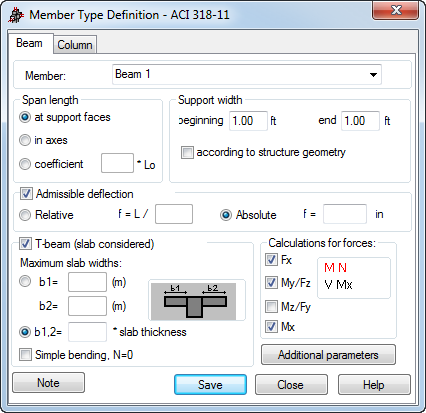
- Member
- Displays the name of the selected member type. The default name is: "Beam" and is assigned the first number available. You can also enter another name in place of the default.
- Span length
-
Contains options that define the calculation length of a beam. There are three ways to define the length:
- At support faces - the distance between the support faces is adopted as a design length.
- In axes - the design length equals the beam length.
- Coefficient, and enter a value - the value becomes the coefficient by which the length at support faces is multiplied to obtain the required value. For example, if you enter a value of 0.25, it means that the required value equals ¼ of the length at support faces. L 0 denotes the beam length between the nodes.
- Support width
- Contains options that define the width of supports. The support width can be defined in two ways:
- Manually - to manually define the support width, enter the required values in the Beginning and End fields.
- According to structure geometry.
If the data concerning support geometry are to be taken directly from the structure model, the according to structure geometry option should be selected. In this case, the support dimensions are calculated on the basis of the projection of supporting element dimensions on the beam axis.
- Admissible deflection
- Defines the maximum deflection calculated according to code requirements for RC beams. It can be defined in two ways.
- Absolute deflection - enter the value of the deflection.
- Relative deflection - the deflection is defined with respect to bar length (e.g. L/200).
If the allowable values are exceeded, the calculation results tables will display.
Note: It is not necessary to define the values of allowable deflection.
- T-beam (slab considered)
- If T-beam (slab considered) is selected, the design of T-beams (beams considered integrally with slabs) is active.
- The edit fields b1 and b2 are available then and you can specify the values of the maximum effective slab widths. If you select the Geometrical verification option, Robot checks during calculations, if the values b1 and b2 are not excessive (that is, geometrically exceed half the span length).
The value b1 corresponds to the panel located in the Y+ part of the member, while b2 - in the Y- part.
Definition of a beam in the slab is justified if the member lies in the plane of the panel (an offset may be additionally defined for the beam). If the member does not lie in the plane of the panel, then it is assumed that the effective slab width equals zero.
Note: T-beams (beams considered integral with the slab) may be defined for two structure types: 3D Shell and Plate; for the remaining structure types these options are not available.Results of RC beam calculations in which a T-beam (beam considered integral with the RC slab) was taken into account, are displayed in the Maps on Bars dialog (the Design tab) and in internal force tables. RC T-beams can also be designed in the RC Beams module.
- Calculations for forces
-
RC beams may be designed for a selected set of forces:
- Axial force Fx
- Bending moment and transversal force My / Fz
- Bending moment and transversal force Mz / Fy
- Torsional moment Mx.
- Additional parameters - click it to view all the codes involving calculation of deflection (for the serviceability limit state). The Additional parameters dialog opens.
- Note - click it display a calculation note.
- Save - click it to add a member type with the defined name and parameters to the list of the formerly-defined RC member types.
Use the buttons at the bottom of the dialog to: