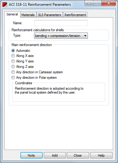
The General tab allows you to define basic slab and shell reinforcement parameters.
Access
- Click
Design
 Required Reinforcement of Slab/Walls - Options
  Code parameters to open the Slab and Shell Reinforcement Type dialog, and then click
 .
.
- Click
 (Slab and Shell Reinforcement Type) to open the Slab and Shell Reinforcement Type dialog, and then click
 .
.
Dialog elements

- Name
- Name of a set of slab and shell reinforcement parameters.
- Reinforcement calculations for shells
-
Type of reinforcement calculations for shells:
- Simple bending (slab).
- Bending + compression/ tension (shell).
- Compression or tension (membrane).
The Reinforcement calculations for shells option reduces a set of internal forces that are considered while calculating panel reinforcement. This can be performed for a complete set of forces (bending + compression/tension), only for bending moments (simple bending), or for membrane forces (compression/tension). Duration of the calculations depends on the selected type of shell calculations. This is only available for shells. When Slab is chosen, bending moments in a slab are considered in reinforcement calculations. In plane stress structure, membrane forces are taken into account.
Note: The verification of user defined settings is not made. Improper use of the option may result in wrong results. - Main reinforcement direction
-
You can select the main slab and shell reinforcement direction (linking directions X of the main reinforcement and Y of the perpendicular reinforcement with the directions of the local coordinate system of a panel). This direction may be defined in the following ways:
- Along the X axis. When selected, the main reinforcement axis will be parallel to the X axis of the global coordinate system.
- Along the Y axis. When selected, the main reinforcement axis will be parallel to the Y axis of the global coordinate system.
- Along the Z axis. When selected, the main reinforcement axis will be parallel to the Z axis of the global coordinate system.
- Any direction in Cartesian system . Once selected, the main reinforcement axis will be parallel to a straight line defined by the user. The line may be defined by entering the coordinates of two points (P1 and P2).
- Any direction in Polar system . Once selected, the main reinforcement direction will be the radial direction in the polar system with a peak in point P1. The other reinforcement direction will be perpendicular to the radial reinforcement (perimeter direction).